|
|
|
Who's Online
There currently are 6043 guests online. |
|
Categories
|
|
Information
|
|
Featured Product
|
|
|
 |
|
|
There are currently no product reviews.
 ;
OK?..manual is complet and helpfull... for repairing such a old and rare boombox like JVC PCM it is necessary...
;
Super Anleitung. Ordentliche Auflösung. Das ganze noch in Deutsch wäre zu schön. Alle Datenblätter sind sauber Kopiert und alle Leitungswege sind sauber ausgeführt
;
Thanks God for the internet and thanks for the service like this - proffessional solution on time.
;
About the service it's very fast and reliable. About the manual the quality is high enough to read even the tiniest details on the wiring diagrams so you can't ask much more than that, let it alone for a manual of a product from 20 years ago. Thank you, very satisfied.
;
The downloaded quality was as good as the orignial
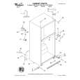
STANDARD NOTES FOR SERVICING
Circuit Board Indications
1. The output pin of the 3 pin Regulator ICs is indicated as shown.
How to Remove / Install Flat Pack-IC
1. Removal
With Hot-Air Flat Pack-IC Desoldering Machine: 1. Prepare the hot-air flat pack-IC desoldering machine, then apply hot air to the Flat Pack-IC (about 5 to 6 seconds). (Fig. S-1-1)
Top View Input Out In
Bottom View
2. For other ICs, pin 1 and every fifth pin are indicated as shown.
5 Pin 1
10
3. The 1st pin of every male connector is indicated as shown.
Fig. S-1-1
2. Remove the flat pack-IC with tweezers while applying the hot air. 3. Bottom of the flat pack-IC is fixed with glue to the CBA; when removing entire flat pack-IC, first apply soldering iron to center of the flat pack-IC and heat up. Then remove (glue will be melted). (Fig. S-1-6) 4. Release the flat pack-IC from the CBA using tweezers. (Fig. S-1-6) CAUTION: 1. The Flat Pack-IC shape may differ by models. Use an appropriate hot-air flat pack-IC desoldering machine, whose shape matches that of the Flat Pack-IC. 2. Do not supply hot air to the chip parts around the flat pack-IC for over 6 seconds because damage to the chip parts may occur. Put masking tape around the flat pack-IC to protect other parts from damage. (Fig. S-1-2)
Pin 1
Pb (Lead) Free Solder
Pb free mark will be found on PCBs which use Pb free solder. (Refer to figure.) For PCBs with Pb free mark, be sure to use Pb free solder. For PCBs without Pb free mark, use standard solder.
Pb free mark
3-1
TVN_SN
|
|
|
> |
|