I purchased the unit from a private party and the original owners manual was not available. Having the ability to download it was extremely helpful and clarified operating the equipment immensely. This is a complicated unit and without the manual I would not have been able to maximize it's potential. Thank you.
Being a user of older radios of many kinds, preferring them over more modern rigs, this manual was invaluable in the programming of my two. I now know for certain what the assorted buttons functions are, and am very grateful to have found this excellent site. Many thanks for your assistance, Tony.
5 star quality on these downloadable manuals. Easy to read and all the information is there. A must when doing a custom install or needing to service your precious old school electronics.
Text excerpt from page 13 (click to view)
Installation
Mounting accessories included
1 deflector 1 coupling ring � 100 mm (EFI 635) or � 120 mm (EFI 640) 2 plastic washers for the spacer 4 wall dowels (screw anchors) 2 screws 5 x 45 with cylindrical heads for use on walls (lower fixing) 2 screws 5 x 45 countersunk for wall use (fixing the hooks) 2 hooks 1 Allen wrench 1 screw 2.9 x 9.5 (ONLY EFI 635 - to affix the deflector on the outlet hole) 2 screws 3.5 x 9.5 (to affix the spacer to the cooker hood) 2 screws 4.2 x 35 (ONLY EFI 635 - to fix the hood to the top of a wall cabinet) 2 screws 2,9 x 13 (ONLY EFI 640 - to fix the deflector to the hood or to the top of a wall cabinet) 4 screws 4.5 x 16 (to affix the cooker hood sideways) 8 screws 4.5 x 13 (to affix a wooden panel to the cabinet door).
I
I
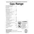
Fig. 9
� 2,5mm x 6mm max
N3 J L L
K
6mm
Fixing a furniture door to the visor
� Remove the extraction grille. � Remove the visor (freeing the locking releases I-Fig.9). � Apply the drill holes diagram N3 on the rear of the furniture door (Fig. 10,J-the arrow on the diagram should face the upper border of the furniture door), perform blind holes as indicated (K-Fig. 10). � Place the visor over the furniture door and affix with 8 screws (Fig. 10,L). � Refit the cover on the cooker hood firstly in the upper track (Fig. 11-M1), then in the lower track (Fig. 11-M2). � Where the cooker hood is provided with revolving locking releases these should be turned in the opposite direction of the release to ensure that the visor is not unintentionally released during normal use of the cooker hood. Fig. 9.