A comprehensive Operating and Service Manual. All schematics are complete and easy to read. The PCB drawings and complete parts list are very helpful. I would definitely recommend this manual.
Genuine Toshiba owner's manual. Couldn't really ask for more. And written in understandable English in contrast to a few recent experiences I have had with manuals for other equipment other than Toshiba but made in China and written in "Chinglish"!
I purchased a vintage Sony mixer off eBay and within the hour was able to locate and purchase the manual for it.I mean really,where else can you find a manual for a product made in 1983!? It was easy to find and purchase/download the manual I needed.I will use this site again for other equipment I have! Great site!
manual de usuario perfecto y completo de buena calidad de impresion y muy detallado ideal !
Text excerpt from page 22 (click to view)
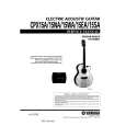
300 mm.
WALL FACE
BACK OF COOKER
480 mm.
100 mm.
LEVELLING FEET
ENGAGEMENT EDGE FOR STABILITY BRACKET
A
PENCIL LINE ON THE FLOOR 245 mm.
BASE OF COOKER
FO 2434
PLAN VIEW OF THE COOKER
SIDE VIEW OF THE COOKER
Fig. 2
Dimensions are given in millimeters
Fitting the Stability Bracket (Not supplied)
If the cooker has to be installed with a flexible supply pipe, it is necessary that a stability device is fitted. (See safety Requirements: Page 20). If a stability bracket is to be fitted by the installer, these instructions should be read in conjunction with the leaflet packed with the stability bracket. Place cooker in its intended position and level cooker. Mark off 295mm (11 1/2") from the right hand side of the cooker as shown, this is the centre line of the bracket fixing. Draw a line 100mm (4") from the front edge of the levelling feet (see Fig. 2) and remove cooker from its position. Mark off 480mm (19") back from this line on the centre line of the bracket to locate the front edge of the lower bracket. Fix lower bracket (with two fixing holes) to the floor, then measure height from floor level to engagement edge on back of cooker, dimension 'A' of Fig. 2. Assemble upper bracket to lower bracket so that underside of bracket is dimension 'A' +3mm (1/8") above floor level. Re-position cooker and check that top bracket engages into cooker back to a depth of 75mm (3"), as shown in Fig. 2. Should the stability bracket currently installed not allow the cooker to stand correctly, ask the installer to replace it with the correct type.
Connecting to Gas
This cooker is designed to be installed with an appliance flexible connection. Connection is made to the RC 1/2 (1/2" B.S.P.) threaded entry pipe located just below the hotplate level on the rear right-hand side of the cooker. Check for gas soundness after connecting the gas supply. The gas bayonet connector must be fitted in the shaded area indicated in the diagram. Take into account that it must be possible to pull the cooker forward sufficiently. The hose must not get caught on the stability bracket. Note: For certain types of gas bayonet connection used, it may not be possible for the appliance to be pushed fully back to the wall stops. Important: Flexible tubing MUST comply with BS.669 Current Edition.