|
|
|
Who's Online
There currently are 6043 guests online. |
|
Categories
|
|
Information
|
|
Featured Product
|
|
|
 |
|
|
There are currently no product reviews.
 ;
Good pdf of the service manual for this unit. Includes disassembly instructions, full schematics, board layouts, parts lists and diagnostic information. Some information is in the pdf twice (single pages, and split pages), but that could be how it was originally generated by panasonic, or perhaps the idea is to make it eaiser to put onto 8.5 x 11" pages.
Information was exactly what I needed. Delivery was overnight (less than 12 hours) and I was happy with the process.
;
5 STARS for FAST DELIVERY, BEST PRICES and QUALITY PRODUCT. Item was exactly as described with superb resolution. Will definitely source all my future requirements from this website. Thanks a lot owner-manual.com!
;
OEM manual provided all schematics, board layouts and component specs necessary to facilitate unit maintenance. All pages were clear and readable.
;
Good condition and quality. Hard to find anywhere in Internet, only on this site.
 ;
Exactly what I needed to be able to bring the amp back to life... will come back to this site the next time I need schematics.
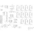
Programmable power supplies
(Processor schematic page 3) Various voltages required by different types of EPROMs are generated by two programmable power supplies. Half of U36, Q1, Q3, Q4, and Q6 are the active components in the VPP supply. VPP has a range of zero to +27 volts, the output controlled by the reference voltage VPPREF which is produced by a digitally programmed DAC/sample/hold circuit. The supply circuit is current limited and has a voltage gain which is determined by R93 and R94. Digital signal VPPSEL* must be at logic zero to enable the VPP supply. The other half of U36, Q2 and Q5 make up the VCC programmable supply which has an output range of zero to +8 volts. The gain of the VCC circuit is determined by R97 and R99. VCC is also current limited and the circuit is enabled by a logic zero on VCCSEL*.
Battery backup
(Processor schematic page 3) In order to retain the contents of memory at all times, a three volt lithium battery supplies power to the CMOS RAM through R141 and D26 when the main power is off. When the power is on, the +5v supply powers the RAM through D25.
RESET circuitry
(Processor schematic page 5) The PUP (Power UP) circuitry consisting of active components Q10 and U65 disables writing to RAM when power is off. PUP is connected to all 6264 ICs directly and to the 6116 RAM through U41. PUP is also buffered by U41 to provide a RESET* signal for the microprocessor and certain latches. The PUP circuit is very sensitive to sudden changes in the +5 volt power supply. If the ripple on the +5 line is too great, PUP will trigger and RESET* will go low, resetting the microprocessor.
Microprocessor and memory
(Processor schematic page 1) The 68B09 microprocessor chip (U38) along with the firmware contained in EPROMs U51 and U52 control all operations of the Prommer. The main
Prommer Service Manual
8
|
|
|
> |
|