|
|
|
Categories
|
|
Information
|
|
Featured Product
|
|
|
 |
|
|
There are currently no product reviews.
 ;
This is the 2nd time I download manuals from this website and I can say it's what I was expecting. It contains schematic, layout (decent quality), short description, parts and dissasembly instructions. I recomend it for anyone who wants to repair/modify this device.
;
Very useful Service Manual! With it I was able to identify the damaged pots in my old amplifier, purchase the adequate replacements and make myself the repair.
I have again my old amplifier, still a very good one that I will keep for as many years as I can!
Thanks to Owner Manuals!
;
Good price for the manual and easy to locate on the site and download. Plus, just like the original. Thanks a lot.
;
Genuine Service Manual. Link was available in less then an hour or so. Service Manual contains assembly, PCB layout, complete circuit diagram, Components list etc
;
Great and very well scanned Service Manual, also very fast download - Recomended !
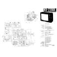
103SW/SW-301/1050SW/SW-501
CONTENTS/DISASSEMBLY FOR REPAIR/ADJUSTMENT
Contents
SPECIFICATIONS ........................................Top cover CONTENTS ............................................................... 2 DISASSEMBLY FOR REPAIR....................................2 ADJUSTMENT ............................................................2 PC BOARD ................................................................ 3 SCHEMATIC DIAGRAM ............................................ 5 EXPLODED VIEW ......................................................7 PARTS LIST................................................................8
DISASSEMBLY FOR REPAIR
< How to remove the front panel >
1. Remove the decoration plate (1) by a pincette to the bottom of the front panel, then remove the 3 screws (2). 2. 103SW/SW-301: Remove the front panel in the upper slanting direction of the arrow (3). 1050SW/SW-501 : Remove the front panel just the frontwards.
2 x3
3
1
1
ADJUSTMENT
No. ITEM INPUT SETTINGS OUTPUT SETTINGS AMPLIFIER SETTINGS ALIGNMENT POINTS ALIGN FOR FIG.
Unless otherwise specified, the individual switches should be set as following : POWER : ON NO SIGNAL INPUT 1 IDLE CURRENT � Connect a DC voltmeter to R611
(a)
VOLUME : 0
VR601
5 mV
(a)
Dc voltmeter
5 mV
R611
2
|
|
|
> |
|