|
|
|
Categories
|
|
Information
|
|
Featured Product
|
|
|
 |
|
|
There are currently no product reviews.
 ;
This is a great site. I placed my order and by the next am it was available for download. Had some problems with some missing copy on some pages. Once I brought the error to the OMC's attention, the issue was resolved. I'll come back again.
 ;
Mi spiace per non poter scrivere in inglese... ma sono veramente soddisfatto del servizio offerto. Grazie..!!
;
The quality of this manual is good. It has all schematics and setup information for both the MDS-B3 and the MDS-B4. The scan quality is quite good, all pages are readable, This service manual also contains scans of the operating instructions from the User manual.
;
Quick site processing. A complete and very useful manual with all details. Thank you!
;
Das Service Manual war von der ersten bis zur letzten Seite sehr informativ und hilfreich. Die Darstellung aller Teile war klar und der Text gut lesbar.
Vielen Dank, das war nicht der letzte Download bei ownner-manuals.com.
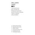
Section V Figure 5-2
Models 691A/692A/693A/694A
AUDIO 0 S C I LLATOR
SWEEP OSCILLATOR
FREQUENCY METER
-
FIXED A T T ENUAT0 R
CRYSTAL
OSCl LLOSCOPE
690-c-7a
Figure 5-2.
Setup f o r Frequency Calibration and External FM Tests (6) The Frequency Meter reading obtained a t 115 line volts should not differ from the reading obtained a t 103 o r 127 line volts by more than 1 Mc for the Models 691A and 692A, 2 Mc for the Models 693A and 694A. q. To test A F frequency deviation, calibration accuracy, centering and center-frequency accuracy, add connection A in Figure 5-2, then proceed as follows: (1) Depress A F. On dial, CW and A F light.
j. Release MARK 1 and depress MARK 2. Tune MARKER 2 to obtain maximum displacement of Oscilloscope dot display. The START/CW dial and MARKER 2 counter readings must agree within *l%,
k. Release MARK 2 and depress A F. Tune Frequency Meter to obtain maximum displacement of Oscilloscope dot display. The START/CW and F r e quency Meter dial readings must agree within *l%.
m. This completes the frequency calibration accuracy t e s t s a t the lowest frequency in the Sweep Oscillator range. To test calibration accuracy a t the high end of the Oscillator frequency range, repeat s t e p s d through k above, starting with the controls s e t as follows: LINE . . . . . . . . . . . . . . . . . . . . . . . . . RF SWEEP SELECTOR . . . . . . . . . . . . . . . CW START/CW . . . . . . high end of Swp Osc range STOP/AF . . . . . . . high end of Swp Osc range MARKER 1 . . . . . . high end of Swp Osc range MARKER 2 . . . . . . high end of Swp Osc range MANUAL SWEEP . . . . . . . . . . . maximum cw POWER LEVEL . . . . . . . . . . . . maximum cw AMPLITUDE MOD s e l e c t o r s . . . . all released n. To test frequency calibration accuracy a t intermediate frequencies in the Sweep Oscillator range, s e t SWEEP SELECTOR to CW and tune START/CWto frequencies of interest. At each frequency, CW dial and Frequency Meter readings must agree within*l%. p. To test frequency stability with line voltage changes: (1) Obtain CW operation at any frequency. (2) Set line voltage to 115. (3) Wait 2 minutes for stabilization, thentune Frequency Meter to obtain maximum displacement of Oscilloscope dot display. Note Frequency Meter reading. (4) Set line voltage to 103 and repeat step (3). (5) Set line voltage to 127 and repeat step (3). 5-4
WWW.HPARCHIVE.COM
(2) Set SWEEP SELECTOR to AUTO, tune START/ CW frequency to the middle of the Oscillator range, tune STOP/AF to the highest numbered MC calibration, and set SWEEP TIME (SEC) to .l-.01 (red knob to LINE SYNC). (3) Set Oscilloscope display width to exactly 10 cm. This display represents maximum A F deviation.
(4) Tune Frequency Meter to measure frequency a t center and a t each end of the Oscilloscope display. Total A F deviation in megacycles, as given by the difference between the frequencies measured at the ends of the Oscilloscope display, must be within 10% (20%, 691A) of the actual A F MC setting with an acceptable additional e r r o r of 1%(2%, 691A) of maximum AF. F o r example, both maximum A F and the highest numbered A F scale calibration on the Model 691A are 100 Mc. Maximum acceptable Model 691A A F e r r o r is then 20% of 100 Mc (the A F setting) plus 2% of 100 Mc (maximum AF), o r k 2 2 Mc total. Similarly, if the A F setting were 50 Mc, maximum acceptable e r r o r would be 20% of 50 Mc (the AFsetting) plus 2% of 100 Mc (maximum A F ) , o r *12 Mc total.
(5) The A F center (CW) frequency must equal the START/CW dial reading within *l%. 02280-1
|
|
|
> |
|