|
|
|
Categories
|
|
Information
|
|
Featured Product
|
|
|
 |
|
|
There are currently no product reviews.
 ;
tres bon document
cela a permis de verifier la connection de l'ecran
merci
salutations
;
The manual was of good quality with high resolution schematic diagrams.
;
The manual was very clear and contained all the information I was looking for. My dishwasher is working again because of this servicemanual!
;
Quality scan, great manual. I solved my problem with this manual.
 ;
The AKAI 1720 model reel to reel tape recorder described in this Manual is quite an old unit - circa late 1960's. As a consequence, the description of the mechanical details - and adjustments thereof - is quite critical. The manual does this quite well. The schematics are also well presented and have detailed PCB overlays. Probably the only negative is that some half-tone detail has been lost from the original manual as it has been scanned in simple B&W.
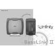
Powered Subwoofer
Basslink II
BASSLINK II DISASSEMBLY
1) Remove �Amplifier Dock� cover; (8) Phillips screws. 2) Remove (10) Phillips screws holding main heatsink/amplifier to enclosure, tapping the heatsink with a rubber mallet may be necessary to loosen it. Pull amplifier from enclosure 3) Remove single 12 pin Molex connector M300 and both pairs of FASTON terminals from the amplifier PCB; do not mix up the two pairs of red/black wires (speaker and A/B). Label if necessary. 4) With the screw cavities facing upwards on the enclosure, remove the (12) Phillips screws holding the enclosure together. 5) Using the opening of the �Amplifier Dock� as leverage, separate the enclosure halves; to completely separate the wiring, remove the 8 pin Molex connector M200 from the Jack/Limiter PCB. 6) If the Gain PCB (Gain/Xover/Base pots) needs to be accessed, there is an additional screw holding the plastic cover on, besides the two exposed ones, that must be removed and is visible after removing the 10" passive radiator (8 Phillips screws) 7) The Jack PCB is not serviceable, as it is attached to the enclosure with adhesive. 8) Reassembly: follow in reverse order, and be sure to not mix the red/black wire pair (speaker and A/B) on the MAIN PCB when you connect them to the FASTON terminals.
9
|
|
|
> |
|