|
|
|
Categories
|
|
Information
|
|
Featured Product
|
|
|
 |
|
|
There are currently no product reviews.
 ;
Awesome manual. Complete diagrams of all board assemblies as well as how to get to each part of the t.v. down to the individual screws and their locations. Get it.
;
perfect copy, im very satisfied, i was need the diagram over the powersupply and
the copy was very sharp
;
This is exactly the service manual I needed.
Complete with all schematics, partslists, PCB layouts and alignment instructions.
This manual covers both the T-4970 en T-488F Onkyo tuner.
 ;
IF PRINTED CIRQUIT BOARD WIRING VIEW WAS ONE TONE LIGHTER, THEN 5 STAR RANK HAS TO BE MY CHOISE.
;
Very usefull, good quality drawings !
Muito útil encontrei todas as informações necessárias.
HP J06-59992A Time Interval Calibrator
Theory of Operation
B1
1-1
'
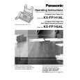
OUTPUT A In-phase OUTPUT B OUTPUT A In-phase/Swap P2 OUTPUT B OUTPUT A Out-of-phase OUTPUT B OUTPUT A Out-of-phase/Swap OUTPUT B
Figure 4-1. HP-1B Command Swnmary.
4-7. INPUT SIGNAL CONVERSION
INPUT
SPLITTER B2 Zero SPLITTER B3 INPUT
B4
180
P2
171
SPLITTER N2
eg
The zero degree power-splitter divides the input signal into two nearly inphase output signals, PI and P 2 Command "Bl" routes the input signal from P l to Output A and P2 to Output B;'732"routes the input from P1 to Output B and P2 to Output A Similarly, the 180-degree power-splitter divides the input into two nearly out-of -phase signals, N 1 and N2. Command "B3" routes the input signal from N 1 to Output A and N2 to Output 8; '%4" routes the input from N 1 to Output B and N2 to Output A Refer to Figure 4- 1 for a diagram illustrating the effect of the HP-IB commands. The commands "Bl -B4",(or switches 1-4 if manually operated), result in four binary states defined by the two bits arriving on A D 4 pin 4 and pin 6. The bit from pin 4, via buffers in A2U 1 energizes the appropriate relays A2K 1 and A2K2, routing the incoming signal from A2J1 to the desired powersplitter. The outputs of the selected splitter are fed to A2K3 where they are connected to Outputs A and B directly, or reversed through a cross-over K3 relay arrangement. Note that the input signal to the splitters and the output signals from the splitters are ac-coupled via blocking capacitors A2C 1, C8, and C9. Table 4- 1 summarizes the J06-59992A operation.
Page 4-2
www.hparchive.com
|
|
|
> |
|