|
|
|
Categories
|
|
Information
|
|
Featured Product
|
|
|
 |
|
|
There are currently no product reviews.
 ;
Speedy transaction with a quick download. Awesome hassle-free service.
;
very poolite and healpful secure transaction thanks allot
;
- Very good scan quality, PERFECT!
- Sehr gute scan Qualitaet, empfehlenswert!
Wolfgang Sundhaus
 ;
Good site, works ok and you get what you order, no problems experienced, got my manual within a day. A++++
;
Original well scanned manual. Got the job done. Microwave problem found & corrected. For $5 and a new magnitron from ebay, it was a cheap and good the first shot fix. Electrical schematics allowed me to mage sure every thing else was ok before cutting and order for parts. Hard to live without.
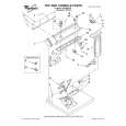
Left side gears
To remove the left side gears
1 2 3 4 5 6 7 8 9 Remove the top cover. Remove the left side cover. Remove the fusing assembly. Remove the screw shown in callout 1, Figure 6-47 on page 185 and remove the black plastic piece. Disconnect all connectors from the paper feed PCB and free the cables from the cable stays. Remove the screw securing the gear cover and remove the cover shown in callout 3, Figure 6-47 on page 185. Remove the fuser motor. Remove the paper path motor. Remove the three clutches: CL2, CL3, and CL4.
10 Remove the four screws (callout 1, Figure 6-55 on page 194) and remove the sheet metal over the gears. 11 Remove the one or two screws (shown in callout 2, Figure 6-55 on page 194) and e-clip (shown in callout 3, Figure 6-55 on page 194) that hold the solenoid assembly in place and then remove the solenoid assembly. 12 Remove any e-clips or bushings necessary to remove the affected gears.
Left side gear replacement
1 2 3 Install the back half of the large double gear shown in callout 1, Figure 6-56 with the small portion of the gear (18T) facing outward. Install the two gears (shown in callout 2, Figure 6-56 on page 194) so they cover the back half of the large double gear. Install the remaining gears and the front half of the large double gear so they appear as shown in Figure 6-56 on page 194.
CAUTION
When reinstalling the solenoid assembly, make sure that the flat parts of the pickup rollers are down and that the plastic spring-loaded gear is fully engaged.
C7085-90921
Chapter 6 Removal and replacement 193
|
|
|
> |
|