|
There are currently no product reviews.
 ;
Everything fine: quick service, no glitch and above all a very good quality of the Pdf file. Thank you!
;
The manual was complete, parts list, adjustment procedures, etc. No worries
 ;
Very usefully, I could find the trouble clearly with that manual.
;
Bon produit. Permet de corriger les couleurs et de redonnez un petit coup de jeune à vos vieilles vidéos. On regrettera juste le manque d'une prise s-vidéo.
;
Quality scan of the actual service manual, just what I was looking for.
103SW/SW-301/1050SW/SW-501
CONTENTS/DISASSEMBLY FOR REPAIR/ADJUSTMENT
Contents
SPECIFICATIONS ........................................Top cover CONTENTS ............................................................... 2 DISASSEMBLY FOR REPAIR....................................2 ADJUSTMENT ............................................................2 PC BOARD ................................................................ 3 SCHEMATIC DIAGRAM ............................................ 5 EXPLODED VIEW ......................................................7 PARTS LIST................................................................8
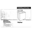
DISASSEMBLY FOR REPAIR
< How to remove the front panel >
1. Remove the decoration plate (1) by a pincette to the bottom of the front panel, then remove the 3 screws (2). 2. 103SW/SW-301: Remove the front panel in the upper slanting direction of the arrow (3). 1050SW/SW-501 : Remove the front panel just the frontwards.
2 x3
3
1
1
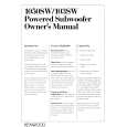
ADJUSTMENT
No. ITEM INPUT SETTINGS OUTPUT SETTINGS AMPLIFIER SETTINGS ALIGNMENT POINTS ALIGN FOR FIG.
Unless otherwise specified, the individual switches should be set as following : POWER : ON NO SIGNAL INPUT 1 IDLE CURRENT � Connect a DC voltmeter to R611
(a)
VOLUME : 0
VR601
5 mV
(a)
Dc voltmeter
5 mV
R611
2
|