|
|
|
Categories
|
|
Information
|
|
Featured Product
|
|
|
 |
|
|
There are currently no product reviews.
 ;
Very quick response. Very good and accurate print quality of the scanned document.
 ;
The service manual was very usable and clear enough to see the individual values of all of the components (unlike some of the service manuals I have gotten in the past from web sites similar to this one). The price was right and the information was greatly appreciated. It helped me with an otherwise very difficult repair. It was much needed and appreciated. A faster turn around on my order would be nice, but I understand the constraints on your staff's time. Thank you for your service.
;
Excellent manual. Helped me out with disassembling and troubleshooting my projector.
;
thanks you are the best.Very good detail, Quick service response. A useful service manual with all details.
;
Great service!!! Polecam gorąco wszystkim zainteresowanym
6
104S CM23 GSIII Go to cover page
Mechanical Instructions
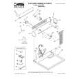
0. General To be able to perform measurements and repairs on the "circuit boards", these unit should placed in the service position first. 1. Remove the rear cover - Open two lids with "-" type screwdriver. Refer to fig2 and fig3. - Remove 4 screws with "+" type screwdriver. 2. Video panel - Remove the metal shielding on rear side of Video panel by desolder lags of metal shielding. 3. Main panel - Disconnect the degaussing coil from Main panel. - Remove the video panel from CRT. - Remove the "screw" of I/F cable from Main panel. - Disconnect the CRT ground "1701" from Video panel. - Disconnect the Hi-Pot cap from CRT. - Disconnect the yoke wire connector "1601" from Main panel. - Slide the main panel out of bottom tray. - Place Main panel in service position as shown in Fig.1. - Mount Video panel again on CRT. - To connect Hi-Pot cap again. - To connect "1701" again. - To connect the yoke wire "1601" again.
lids
lid
Fig.2
screws
screws
Fig. 1
Fig.3
Back
Forward
|
|
|
> |
|