|
|
|
Categories
|
|
Information
|
|
Featured Product
|
|
|
 |
|
|
There are currently no product reviews.
 ;
very good manual with clear electrical schemes. Very helpful to find wat was wrong inside my microwave.
 ;
Hi, thankyou for providing the Nordmende Globetrotter original manufacturer's repair manual. Quality is very good and sharp - the PDF file was comfortably small to download. The only question is: why did it take so long to become ready for download?? Many thanks anyway, I fixed the fault in the radio thanks to the circuit.
regards: Nick
;
This was super service.Ordered this manual and was reading the download an hour later
;
as always, rapid and efficient, very good and clear prints
details clearly visible keep going this way!!!!!!
;
I expect a wonderful result as alaways!!!!!!
Usually is much faster....
6
104S CM23 GSIII Go to cover page
Mechanical Instructions
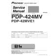
0. General To be able to perform measurements and repairs on the "circuit boards", these unit should placed in the service position first. 1. Remove the rear cover - Open two lids with "-" type screwdriver. Refer to fig2 and fig3. - Remove 4 screws with "+" type screwdriver. 2. Video panel - Remove the metal shielding on rear side of Video panel by desolder lags of metal shielding. 3. Main panel - Disconnect the degaussing coil from Main panel. - Remove the video panel from CRT. - Remove the "screw" of I/F cable from Main panel. - Disconnect the CRT ground "1701" from Video panel. - Disconnect the Hi-Pot cap from CRT. - Disconnect the yoke wire connector "1601" from Main panel. - Slide the main panel out of bottom tray. - Place Main panel in service position as shown in Fig.1. - Mount Video panel again on CRT. - To connect Hi-Pot cap again. - To connect "1701" again. - To connect the yoke wire "1601" again.
lids
lid
Fig.2
screws
screws
Fig. 1
Fig.3
Back
Forward
|
|
|
> |
|