|
|
|
Categories
|
|
Information
|
|
Featured Product
|
|
|
 |
|
|
There are currently no product reviews.
 ;
Quality as promised it arrived fast. No problems what so ever
;
Good scan, very handy and it also includes the user manual. 122 pages in total.
;
This manual was exactly what I needed. Detailed, useful and delivered as promised.
 ;
Great manual good quality really helped in the repair of my Toshiba, thanks
;
Print was clear and easy to read. Thank you Joe joeoldaudio
Power Amplifier
Reference 1210a/1211a
POWER CONNECTIONS
The Reference amplifiers are capable of delivering high power levels, and require a reliable connection to the vehicle�s electrical system in order to perform optimally. See Figure 1 for connection location. Please adhere to the following instructions carefully. GROUND CONNECTION Connect the amplifier�s Ground (GND) terminal to a solid point on the vehicle�s metal chassis, as close to the amplifier as possible. Refer to the chart below to determine minimum wire-gauge size. Sand away any paint from this location; use a star-type-lock washer to secure the connection. POWER CONNECTION Connect a wire (see chart at right for appropriate gauge) directly to the vehicle�s positive battery terminal, and install an appropriate fuse holder within 18" of the battery terminal. Do not install the fuse at this time. Route the wire to the amplifier�s location, and connect it to the amplifier�s positive (+12V) terminal. Be sure to use appropriate grommets whenever routing wires through the firewall or other sheet metal. Failure to adequately protect the positive wire from potential damage may result in a vehicle fire. When you are done routing and connecting this wire to the battery and to the amplifier, you may install the fuse at the battery. The fuse value should be selected based on total amplifier-current draw; see chart at right. REMOTE CONNECTION Connect the amplifier�s Remote (REMOTE) terminal to the source unit�s Remote Turn-On lead using a minimum of 18-gauge wire. If your source unit does not have a remote turn-on connection, connect the amplifier�s (REMOTE) terminal to the vehicle�s accessory circuit. WIRE-GAUGE CHART Amplifier Maximum Model Current Draw AWG AWG 1210a/1211a 115A Minimum Wire Gauge #4 AWG
These recommendations assume 7' � 10' wire runs. If your installation differs markedly, you will need to adjust the wire gauge accordingly.
SPEAKER CONNECTIONS Refer to the application guides on the pages that follow. Speaker connections should be made using a minimum of 16-gauge wire.
NOTE: When using the low-level or high-level inputs, the AUX outputs can be used to pass a full-range line-level signal to another amplifier.
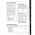
Figure 1.Terminal-connection end plate.
3
|
|
|
> |
|