|
|
|
Categories
|
|
Information
|
|
Featured Product
|
|
|
 |
|
|
There are currently no product reviews.
 ;
Superb rendition. Drawings (schematics) complete and unabridged. I do a great deal of vintage audio restoration. Documentation is essential for successful repairs. I have found sources over the years that offer good documentation, but rarely all that is necessary. Owner's Manuals has filled that void with complete and legible documentation. They have narrowed my "favorites" to a more manageable collection. This Denon manual in particular contained the latest revisions level, and offered alterations favorable to updating the item. The Illustrated Parts Breakdown (IPB) was well enough detailed to simplify part symbols and physical locations. You will not be disappointed!
;
Clear and concise. Saved me a lot of time and money.
;
Superb manual. Exactly what I ordered and made available in a very timely manner.
 ;
very fast detailed and accurate hope to do business again
;
This was precisely what I was looking for. Complete and good quality!
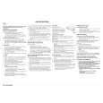
CONVERGENCE CRT CUT-OFF, BACKGROUND AND SUB-CONTRAST ADJUSTMENT
BGR ADJ. 2. Using the remote controller, call NORMAL mode. ADJUSTMENT NO VIDEO signal.
2
14A1-RU 14A2-RU
No. point Adjusting procedure/conditions Waveform and others
CONVERGENC Receive the "Crosshatch Pattern" signal. 1 CRT CUTOFF 1. Switch TV to VIDEO mode,BLUE BACK OFF, with ( To be done (I C BUS 2. Press R/C to set Picture Normal condition.
G adjustment. 1. Turn the 4-pole magnet to a proper opening anIC801.(TP851) R
3.0Vdc
after purity STATIC CONVERGENCE B CONTROL) 3. Connect the oscilloscope to Red OUT from
gle in order to superpose the blue and red colours. Range : 1 V/Div (DC)
RGB R
2. Turn the 6-pole magnet to a proper opening anFig. 5-1 Sweep : 5 msec/Div
0
gle in order to superpose the green colour over 1 V blue and red colours. 4. Adjust SCREEN VR ,so that the tip of signal reach 3.0 Vdc + 0.1 Vdc.
DYNAMIC CONVERGENCE G Adjust convergence on fringes of the B 2 SUB-BRIGHT1. Call " SUB-BRI" in service mode. (Receive CrossFig. 5-2 2 (I C BUS line 1, 2 and 3 have the same darkness
B
NESS hatch pattern with 5 black level windows) screen in the following steps. ADJUSMENT 2. Adjust SUB BRIGHT " bus data in order that a) Fig. 5-1: Drive the wedge at point "a" and swing the deflection coil upward.
b) Fig. 5-2: Drive the wedge at points "b" and "c" RGB CONTROL) wherelse is slightly brighter than line 1, 1 2 3 4 5
c) Fig. 5-3: Drive the "c" wedge deeper and swing R line 4. 1, 2, 3 are in same black level.
swing deflection coil downward. 3 and finally line 5 will be the brighter than G
the deflection coil rightward.
d) Fig. 5-4: Drive the "b" wedge deeper and swing 3 WHITE BAL1. Receive the "Monoscope Pattern" signal. Refer to Page 6.
2. Fix all wedges on the CRT and apply glass Fig. 5-3 ICE MODE 3. Connect DC miliammeter between the TP 602 Y : 0.310 3. Apply lacquer to the deflection yoke lock screw, G 7500°K ( white ). DOWN by volume key.
R
the deflection coil leftward. ANCE SERV2. Press R/C to set Picture NORMAL condition. # 7500° K X : 0.300
tape over them. BGR ADJ. (I2C BUS ) TP 603 ( + ).
CONTROL) 4. Check Beam current should be around 800µA) ( MINOLTA COLOUR ANALYZER
magnet unit (purity, 4-pole, 6-pole magnets) and B 5. Set it to service mode and adjust the DRI-GS, & CA-100) magnet unit lock screw. DRI-BS data to have a colour temperature of *NOTE: Above DATA can be UP/
8
Wedge "a" LUMINATE Y signal. 20"/21" 10cd/m2 120cd/m2
Finally received the Red-only and Blue-only sig6. Receive "WHITE" pattern, WITH BURST signal, nals to make sure there is no other colours on the Fig. 5-4 and set BRIGHTNESS Y by generator, to ** 10 LOW HIGH screen. cd/m2 (MINOLTA CA-100) by reducing 14" 10cd/m2 200cd/m2 7. Adjust "CUT-R" & "CUT-G" to get 7,500. Then go
back NORMAL mode (HIGH BRIGHT**) to check * 7500° K About
100° colour temperature. If out of range, back to (1). DRI-GW="DRI-GS"DATA-5
DRI-BW="DRI-BS" DATA-5
Lacquer Note: This adjustment must be done after Wedge "b" "c"
warming up the unit for 30 minutes or longer with a beam current over 500µA. * ADJUST DRI-GC/GW, DRI-BC/BW as following DATA, after finishing DRI-BS and DRI-GS DATA ADJUSTMENT.
6-pole magnet DRI-BW="DRI-BS"-7*DRI-RC=25*, DRI-
4-pole magnet DRI-RW=32 (FIXED), DRI-GW="DRI-GS"-7*,
BC="DRI-BS", DRI-GC="DRI-GS"-7* CRT neck 4 Maximum 1. Receive the "Monoscope Pattern" signal. beam check 2. Press R/C to set Picture NORMAL condition.
Purity magnet (Full Scale: 3 mA Range) Lacquer 40cm and TP602 (�).
3. Connect the DC miliammeter between TP603 (+) 4. Beam current must be within 800 ± 100 µA.
8-1 8-2
|
|
|
> |
|