|
|
|
Categories
|
|
Information
|
|
Featured Product
|
|
|
 |
|
|
There are currently no product reviews.
 ;
Excellent printing quality.
A complete and very usefull service manual with all details.
GREAT SERVICE AT VERY LOW PRICE!
A++
;
Best help everywhere i got from here. My audio medicinman was happy to get this manual from me. So he could repair my pioneer perfectly. Thanks
R O
;
It was very usefull, it is clear the quality is super, the price I paid is very afordable.
Generally speaking Iam very happy with this company.
;
The manual was exactly what I needed, Good quality scans too. superb.
;
I am so happy found this site as it consists of so many Manuls and easy to aquire. This onei s exactly what I wanted and much more as it has info on not only how to use the tuner but how to repair it as well. I will come here 1st before purchasing else where! Thanks owner-manual.com!
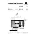
TROUBLE SHOOTING TABLE (Continued)
NO RASTER
CIRCUITS TO BE CHECKED: Tuner. PIF. Automatic Gain Control. Contrast, Brightness and Sound controls ?
Normal Replace the fuse.
14B2-TX/20B2-TX 21B2-TX
PICTURE, NO SOUND
Check F701. Blown out. (5V), (33V) Power Source. Does the noise level increase at max.
Noise increases but no signal is received.
(Approx. 310V at 220V AC)
No snow noise.
The fuse is blown out again.
Check T701 pin (7) voltage Abnormal
Check IC701, D701 and C707. NO YES
Normal 5V. BT must be approx. 32V D709.
Check the tuner supply voltage LB must Check R701, R707 and IC801 ? and CH preset data check.
Does signal appear at pin (40) of
Secondary Main+B Does signal Check IC801 and
Normal T701 (17) voltage appear at pin (38) its related circuit.
Check the tuner AGC NO YES at TP201. D758, IC702, IC753 Check CRT connector D1001 (Power LED Green) Check Q204 and Normal Abnormal
NO its related circuit.
D1001 (Power LED Red) Check pin (27) of IC801, Tuner and
Abnormal (Approx. 115V) Normal of IC801 ?
and R712. K1-K5 bias. turns on. YES
Abnormal Normal
Check pin (38) of on or turns ON/OFF. Check pin (1) of SF201 and IC801. Tuner's related circuit.
Checking the protector circuit.
R615 R618. Check pin (37) of IC801 and C878. IC801. related circuit.
Check ON/OFF ON
related circuit.
18
YES CIRCUITS TO BE CHECKED:
Bus error mode Does horizontal circuit See Fig.1 NO oscillate ?
Check IC801, IC751, D605 (44) of IC801. and Q601. » Sound Detector Circuit.
» Sound system pins (28) and » Sound Switch and Att. NO Does signal appear at pin (28)
NO SOUND
Control. (44) IC801 ? of IC801?
If a bus error happens, LED RED [pin (11) of IC801 LOW] indicator starts blinking and the
» Audio Output Circuit. power is turned off. YES The power key (CHANNEL button on the TV) is still effective. (Signal)
YES NO
Fig.1 EEPROM IC1003
V/C/J IC801
(6) and (8) of IC301 ? Check IC801. peripheral circuit.
NO (M24C08) Does signal appear at pins Check C356 and YES (IX3412CE)
AV Switch IC401
(M52797SP)
PLL Tuner TU201 2s 0.5s
(VTST5HD84)
P301 connector of Check Q301, pins (4) and (6) IC301 circuit. of IC801 and peripheral circuit.
18-1 18-2
|
|
|
> |
|