|
|
|
Categories
|
|
Information
|
|
Featured Product
|
|
|
 |
|
|
There are currently no product reviews.
 ;
This manual was the factory original. Excellent value and contained all the details I needed. Easy dowwnload provided the information when I needed it.
 ;
Impeccable, document très complet. Perfect, i get all i need. All schematic are correct. Thanks
;
The manual is of better quality compared to other. I found it less expensive and therefore it it is the best buy cost vs quality.
;
I bought the service-manual of the sony ICB-1020(an old transmitter-receiver) at "www.Owners-Manual.com", I found the service-manual for a fairly cheap price(in comparison with other sellers). I filled in some questions, payed the order with Ideal, and within 24 hours I had my service manual. I was very happy:In no time I had my service-manual and everything, but literally everything was noted down in the manual; the electronic scheme, the parts list, etcetera.
A very practical, reference-document.
;
This comprehesive service maual was greatly appreciated, as was the digital download.
ADJUSTMENT PRECAUTION: PURITY ADJUSTMENT Make sure TV Set is in "Normal Condition" before switch to service mode for adjustNo. point Adjusting procedure/conditions Waveform and others ment.
1 PURITY ADJ. 1. Receive GREEN-ONLY signal. Adjust the beam current to about 500 µA. 2. Degauss CRT enough with the degausing coil.
a b
Note: Follow the Job Instruction Sheet to adjust the magnetic field. 3. Maintain purity magnet at the zero magnetic field and keep the static convergence roughly 1 Tuner IFT 1. Get tuner ready to receive the CH. E 9 adjusted. ( PRESET ) signal,but with no signal input. rank A requirements. the tuner antenna. ( RF SWEEP )
100k 75ohm
PIF ADJUSTMENT
No. point Adjusting procedure/conditions Waveform and others
2. Connect the sweep generator's output cable to 10k 1n60 1000p through microscope. Adjust landing to the
Oscilloscope IF OUT
Adjust the PLL data. 4. Observe the points a, b as shown in Fig. 4-1 Fig. 4-1 5. Orient the raster rotation to 0 eastward. 6. Tighten up the deflection coil screws. 3. Adjust the sweep generator's to 80dBuV. 4. Connect the response lead ( use LOW IMPED-
ANCE probe with wave detector ; see Fig.1 ) to » Tightening torque: 108 20 N (11 ± 2 kgf) A the tuner's IF output terminal. ( This terminal Fig.1 7. Make sure CRT corners landing meet the A rank requirements. If not, stick the magnet sheet must have the probe alone connected ). to correct it. 5. Set the RF AGC to 0 6 V no saturation with B Note: This adjustment must be done after the waveform. longer with a beam current over 500 µA. shown in Fig. 2. -1.5+/-0.8dB Fig.2 * For the following colours press R/C RGB key to Note: Be sure to keep the tuner cover in position Fig. 4-2
E-9 CH
6. Adjust tuner IF coil to obtain the waveform as A = B
P C warming up the unit for 30 minutes or
during this adjustment. change. Rank "A"
(on right of the CRT)
Green-only Blue-only Red-only
2 RF-AGC 1. Receive "PAL COLOUR BAR" signal. Note: For the 50 ohm signal
TAKE OVER » Signal Strength: 57 ± 1 dBµV (75 ohm open) strength gauge, when not POINT AD2. Connect the oscilloscope to TP201(Tuner�s AGC u s g 0 / 7 5 i m p d a n c e
7
7-1 7-2
(I C BUS 52±1dBµV(75 ohm open), in-2 CONTROL) Oscilloscope stead of 57±1dBµV (75 ohm
A Signal-colour screen cleared
JUSTMENT Terminal) as shown in Fig. 3. adapter, signal strength is
B + TP210 open).
0.1V Precaution: The loss of using
� impedance adapter A = B Fig. 4-3
Rank "A" �
Bias box TV Set
+
» Bias box: About 4.5 V (on left of the CRT)
Fig. 3 * Press R/C RGB key for 1 sec-
3. Call "AGC" mode in service mode. Adjust the ond in NORMAL MODE, the
"AGC" bus data to obtain the Tuner output pin colour will change to RGB mono drop 0.1V below maximum voltage. colour mode.
4. Change the antenna input signal to 63~67dBµV,
and make sure there is no noise. The TEXT "R. G. Cy" Key
5. Turn up the input signal 90~95 dBµV to be sure can be directly use to change
that there is no cross modulation beat. to other colours screen.
14D1-S/G/W 14D2-S/G
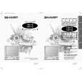 $4.99 14D1S SHARP
Owner's Manual Complete owner's manual in digital format. The manual will be available for download as PDF file aft…
|
|
|
> |
|