|
|
|
Categories
|
|
Information
|
|
Featured Product
|
|
|
 |
|
|
There are currently no product reviews.
 ;
The delivery of this manual was very fast, less than 8 hours. The manual is very clear and concise, and helped a great deal in the repair and final setup of the Hitachi HMA-G2 Amplifier.
;
Great service. The manual was exactly what I was looking for: schematic + layout. I managed to fix the player. Highly recommended!
 ;
At $5,00 certainly good bang for your buck. Includes electric schematics as well as exploded parts view + parts list for reordering. Unfortunately no details on the PCB contents or working, but then again, this is not overly complex. Best bonus: this manual does contain the heavily searched for LED error codes as well as descriptions for test operation. Haven't gotten around to fixing the machine yet, one thing the manual won't do for you is getting it out of the kitchen assembly :-(
;
It`s not your fault tear down is rather incomplete. It doesn`t have complete instructions as to deconstruction for repair.
;
THANK YOU FOR A GOOD TRANSACTION, NICE COPY, CLEAR
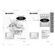
ADJUSTMENT PRECAUTION: PURITY ADJUSTMENT Make sure TV Set is in "Normal Condition" before switch to service mode for adjustNo. point Adjusting procedure/conditions Waveform and others ment.
1 PURITY ADJ. 1. Receive GREEN-ONLY signal. Adjust the beam current to about 500 µA. 2. Degauss CRT enough with the degausing coil.
a b
Note: Follow the Job Instruction Sheet to adjust the magnetic field. 3. Maintain purity magnet at the zero magnetic field and keep the static convergence roughly 1 Tuner IFT 1. Get tuner ready to receive the CH. E 9 adjusted. ( PRESET ) signal,but with no signal input. rank A requirements. the tuner antenna. ( RF SWEEP )
100k 75ohm
PIF ADJUSTMENT
No. point Adjusting procedure/conditions Waveform and others
2. Connect the sweep generator's output cable to 10k 1n60 1000p through microscope. Adjust landing to the
Oscilloscope IF OUT
Adjust the PLL data. 4. Observe the points a, b as shown in Fig. 4-1 Fig. 4-1 5. Orient the raster rotation to 0 eastward. 6. Tighten up the deflection coil screws. 3. Adjust the sweep generator's to 80dBuV. 4. Connect the response lead ( use LOW IMPED-
ANCE probe with wave detector ; see Fig.1 ) to » Tightening torque: 108 20 N (11 ± 2 kgf) A the tuner's IF output terminal. ( This terminal Fig.1 7. Make sure CRT corners landing meet the A rank requirements. If not, stick the magnet sheet must have the probe alone connected ). to correct it. 5. Set the RF AGC to 0 6 V no saturation with B Note: This adjustment must be done after the waveform. longer with a beam current over 500 µA. shown in Fig. 2. -1.5+/-0.8dB Fig.2 * For the following colours press R/C RGB key to Note: Be sure to keep the tuner cover in position Fig. 4-2
E-9 CH
6. Adjust tuner IF coil to obtain the waveform as A = B
P C warming up the unit for 30 minutes or
during this adjustment. change. Rank "A"
(on right of the CRT)
Green-only Blue-only Red-only
2 RF-AGC 1. Receive "PAL COLOUR BAR" signal. Note: For the 50 ohm signal
TAKE OVER » Signal Strength: 57 ± 1 dBµV (75 ohm open) strength gauge, when not POINT AD2. Connect the oscilloscope to TP201(Tuner�s AGC u s g 0 / 7 5 i m p d a n c e
7
7-1 7-2
(I C BUS 52±1dBµV(75 ohm open), in-2 CONTROL) Oscilloscope stead of 57±1dBµV (75 ohm
A Signal-colour screen cleared
JUSTMENT Terminal) as shown in Fig. 3. adapter, signal strength is
B + TP210 open).
0.1V Precaution: The loss of using
� impedance adapter A = B Fig. 4-3
Rank "A" �
Bias box TV Set
+
» Bias box: About 4.5 V (on left of the CRT)
Fig. 3 * Press R/C RGB key for 1 sec-
3. Call "AGC" mode in service mode. Adjust the ond in NORMAL MODE, the
"AGC" bus data to obtain the Tuner output pin colour will change to RGB mono drop 0.1V below maximum voltage. colour mode.
4. Change the antenna input signal to 63~67dBµV,
and make sure there is no noise. The TEXT "R. G. Cy" Key
5. Turn up the input signal 90~95 dBµV to be sure can be directly use to change
that there is no cross modulation beat. to other colours screen.
14D1-S/G/W 14D2-S/G
 $4.99 14D2S SHARP
Owner's Manual Complete owner's manual in digital format. The manual will be available for download as PDF file aft…
|
|
|
> |
|