|
|
|
Categories
|
|
Information
|
|
Featured Product
|
|
|
 |
|
|
There are currently no product reviews.
 ;
Excellent, fast delivery, excellent product. Good luck!
;
This manual is for the usa model only. But it is clear
, accurate and comprehensive, including board layouts and schematics.
I found it extremely useful for my mitsubishi dp-86da, but the same diagram would also work for the realistic lab5000 and hi fi 80. Thanks.
;
Great to have extra resources for Service Manuals, Now days you can really not trouble shoot efficiently without one , Wayne at IRIONS TV & ELECTRONICS REPAIR Clearwater , Fl. 33755 727-446-7955
 ;
For five bucks you can barely buy a hamburger. Or for the same five bucks you can buy a service manual. Much more useful. (and better for your health, depending on where you buy your hamburgers).
Yes, there are free manual sites out there, but if they don't have what you want, you have to pay.
And five bucks isn't much. Not for full specs, schematics and adjustment and parts replacement procedures.
My only criticism is that grayscale illustrations aren't well rendered, but I've seen worse.
Schematics and text are clear.
I'll be happy to purchase from here again.
Mike
[email protected]
;
Impressively thorough. Even the simple operators manual helped me "fix" one of the 2 CD players in the unit. This unit reads CD's from the top so they should be installed in the magazines "upside down" from typical CD players. The CD player service manual helped me unjam a stuck carriage because somebody transported the box laying down loaded with CD's. A little lens cleaning & the player now works well! Thanks for you help at a great price! Joe
1-2
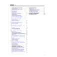
TABLE OF CONTENTS
Page Front page .............................................................................. 1-1 Table of contents ................................................................... 1-2 Survey of sets and features ................................................... 1-3 Survey of sets and boards ..................................................... 1-4
V. EXPLODED VIEWS AND PARTS LISTS
Mechanical parts list .............................................................. 5-1 Electrical parts list .................................................................. 5-4
III. SCHEMATICS
Interconnection wiring diagram .............................................. 3-1 Block diagram - Tuner1, TV ................................................... 3-2 Block diagram - Power Supply, Large Signal,TXT ................ 3-3 Block diagram - In/Out, Audio ................................................ 3-4 Block diagram - Tuner2, Video .............................................. 3-5 Block diagram - Central Control, Deck Electronics ............... 3-6 TV Board (TVB) Power Supply (PS) - Schematic diagram .............................. 3-7 Deflection (LS) - Schematic diagram ..................................... 3-8 Tuner 1 (TU1) - Schematic diagram ...................................... 3-9 TV Processing (TV) - Schematic diagram ........................... 3-10 Input/Output (IO_1) - Schematic diagram ........................... 3-11 View Selector Audio (SF) - Schematic diagram .................. 3-12 Amplifier (AMP) - Schematic diagram ................................. 3-13 Teletext Controller (COTV) - Schematic diagram ................ 3-14 Recorder Unit Board (RUB) Power Supply (PS) - Schematic diagram ............................ 3-15 Central Control 1 (AIO1) - Schematic diagram .................... 3-16 Central Control 2 (AIO2) - Schematic diagram .................... 3-17 Deck Electronics (DE) - Schematic diagram ....................... 3-18 Clock, VPS, Buzzer (CVB) - Schematic diagram ................ 3-19 Tuner 2 (TU2) - Schematic diagram .................................... 3-20 Sound Processing (AP) - Schematic diagram ..................... 3-21 FM-Audio Processing (AF) - Schematic diagram ................ 3-22 Linear Audio Processing (AL) - Schematic diagram ............ 3-23 Video Signal Processing (VS) - Schematic diagram ........... 3-24 SECAM Processing (VSEC) - Schematic diagram ............. 3-25 Head Amplifier (HA) - Schematic diagram .......................... 3-26 Headphone, Front-AV Board (HPAV) Schematic diagram .............................................................. 3-27 CRT-Board (PT) Schematic diagram .............................................................. 3-28 Audio Board (APDOD) Pre Amplifier (ACO) - Schematic diagram ........................... 3-29 Audio Processing (AF2) - Schematic diagram .................... 3-30 Sound Feature Board (SFD) Schematic diagram .............................................................. 3-31 Cinch Out, Scart 2 Board (DOSCD) Schematic diagram .............................................................. 3-32 Keys & Display Board (KB1D) Schematic diagram .............................................................. 3-33 Key Board (KB2D) Schematic diagram .............................................................. 3-34 Mainsfilter Board (MFSWD) Schematic diagram .............................................................. 3-34 Variant list Tuner 1 - TV Board (TVBAD) .............................................. 3-35 Tuner 2- Recorder Unit Board (RUBAD) ............................. 3-36
IV. CIRCUIT BOARD DIAGRAMS
Sound Feature Board (SFD) .................................................. 4-1 Mainsfilter Board (MFSWD) ................................................... 4-1 Audio Board (APDOD) ............................................................ 4-1 TV Board (TVBCD), CRT Board, HPAV Board, Switch Board .. Components side .................................................................... 4-2 Copper side ............................................................................ 4-5 TV Board (TVBDD), CRT Board, HPAV Board, Switch Board .. Components side .................................................................... 4-6 Copper side ............................................................................ 4-9 Recorder Unit Board (RUB2D) Components side ................................................................. 4-10 Copper side .......................................................................... 4-11 Cinch Out, Scart 2 Board (DOSCD) .................................... 4-12 Keys & Display Board (KB1D, KB2D) ................................ 4-12
|
|
|
> |
|