|
|
|
Categories
|
|
Information
|
|
Featured Product
|
|
|
 |
|
|
There are currently no product reviews.
 ;
This is a good quality scan of the service manual which includes an assembly diagram, block diagram, schematic, and parts list. Exactly what is needed to repair my KR-V55R receiver.
;
Excellent concise manual. All needed information was included. Typeface and diagrams were clear. Very fair price considering what others are charging. Many thanks
 ;
Response is a little slow- I had to wait 12 hours to receive download link but it says that it may take up to 24hrs.
Manual is old and was not produced in PDF- scanned copy is exellent.
Overall- value for money- I recommend
;
Excellent quality and quickly delivered manuals at a fair price. Great care is taken in the reproduction process. Even photographs and highly detailed drawings are as clear as in the original. That cannot be said for some freelance manual copies I have obtained from the web. If you have exhausted your internet search of technical manuals, try Owner-Manuals.com. If they do not have it, I do not think it exists. Perhaps, if requested, they may be able to find it. Their resources are certainly greater than most. Shopping here certainly beats waiting for months or years for the manual you seek to appear in an internet auction or garage sale.
;
Very detailed product, also it is a scanning from original, very useful if you have to service this type of amplifier ! Very good product, very hard to find!
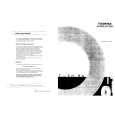
Alignment and Adjustments
4-3-3 High Voltage Check
4. Input a black and white signal.
CAUTION: There is no high voltage adjustment on this chassis. The B+ power supply must be set to +125 volts (Full color bar input and normal picture level).
5. Fully demagnetize the receiver by applying an external degaussing coil. 6. Turn the CONTRAST and BRIGHTNESS controls to maximum. 7. Loosen the clamp screw holding the yoke. Slide the yoke backward or forward to provide vertical green belt. (Fig. 4-2). 8. Tighten the convergence yoke. 9. Slowly move the deflection yoke forward, and adjust for the best overall green screen. 10. Temporarily tighten the deflection yoke.
1. Connect a digital voltmeter to the second anode of the picture tube. 2. Turn on the TV. Set the Brightness and Contrast controls to minimum (zero beam current). 3. The high voltage should not exceed 27.5KV. 4. Adjust the Brightness and contrast controls to both extremes. Ensure that the high voltage does not exceed 27.5KV under any conditions.
4-3-4 FOCUS Adjustment
1. Input a black and white signal. 2. Adjust the tuning control for the clearest picture. 3. Adjust the FOCUS control for well defined scanning lines in the center area of the screen. 11. Produce blue and red rasters by adjusting the low-light controls. Check for good purity in each field. 12. Tighten the deflection yoke.
4-3-5 Cathode Voltage Adjustment (Screen Adjustment)
1. Enter the FACTORY mode. 2. Select the G2-ADJUST. 3. Adjust the screen VR(on the FBT) so that �SCREEN ADJUST : NG(Red or Blue)� becomes �SCREEN ADJUST : OK�. When the color of �SCREEN ADJUST� is red, the cathode voltage is low and when blue, it is high.
4-3-6 Purity Adjustment
1. Warm up the receiver for at least 20 minutes. 2. Plug in the CRT deflection yoke and tighten the clamp screw. 3. Plug the convergence yoke into the CRT and set in as shown in Fig. 4-1.
4-5
|
|
|
> |
|