|
|
|
Categories
|
|
Information
|
|
Featured Product
|
|
|
 |
|
|
There are currently no product reviews.
 ;
Thanks for offering this item at such a good price. Proved handy in identifying the part I was looking for my set.
Thanks again.
;
This is the original manufacturers service manual, with detailed info on the circit boards, explosion drawings of all parts in assembly order, and tuning instructions. The only thing missing is the information on the dimensions of the various drive belts. mail me if you need them. gcrossman_at_aol.com
;
Ordered service manuel for a hard to find plasma tv - your company made it easy to find and purchase - I will use you again
Thanks for your help
 ;
This is a high quality manual with clear schematic and components layout diagrams ; with service procedure included.
;
This service manual for the Kenwood KT-990D was reproduced really well ,is very legible and manual is complete.Combined with the low price paid,in the future,I will be checking Owner-Manuals.com any time I need a manual.
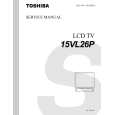
2-4. Sensor PC Board
1. Remove one screw (1) and remove the connector (2) from the one location, then remove the sensor PC board (3).
Screw (1)
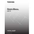
2-5. LCD Rear Cover
1. Remove the front panel, the LCD panel and the inverter PC board. (Refer to item 1-1, 1-2 and 1-3.) 2. Remove two screws (1), then remove the support (2). 3. Remove two screws (3) and remove the LCD rear cover (4) in a vertical position. Note:
Connector (2)
� If not removed when in a vertical position, the hinges may become deformed.
Sensor PC board (3)
LCD rear cover (4)
Screws (3)
Fig. 1-2-9
Note: � When attaching the sensor PC board (3), bundle the wires with the band (4) and insert into groove then attach the sensor PC board (3) from the top.
Sensor PC board (3) Band (4) Wires
Support (2) Screws (1)
Guide
Fig. 1-2-11
Place the bundled wires (4) into this groove and attach the sensor PC board (3) on the top.
Fig. 1-2-10
1-6
|
|
|
> |
|