|
|
|
Categories
|
|
Information
|
|
Featured Product
|
|
|
 |
|
|
There are currently no product reviews.
 ;
Excellent just what I needed to replace the electrolytic caps and make this old gem a beauty again. Was as scan of the original photocopied service manual.
;
It was helpful to get schematic with waveforms in important points and lot of service information. Manual is good quality, fast delivered. Of course it is hardcopy of paper one with all its disadvantages.
 ;
I want to give you a real heads-up for your desire to enable such people as I to acquire the information I need to maintain the older types of equipment such as this Akai HXA351W. You do a swell job with all the processes you have to perform so I can have a legible, thus usable
document which does not send me crazy trying to figure out the blurry text of a bad copy.
Very well done, Thomas.
;
This manual is very well presented and after printing out looks about as close to an original as I think you can get. The quality is second to none.
The content of the manual is comprehensive and I think it would be well suited to an audio repair professional which I'm not but I did find it very informative and helpful.
The cost of the manual is more than covered by the money I'll save when I change the keep memory battery now I have the relavant info.
Very pleased with my purchase and can recommend it wholeheartedly as I can other manuals I've downloaded from this site.
Regards
Limey Alex
;
Complete manual including mechanical part in good pdf quality. Shaded greys of the pcb due to pdf not perfect but usable.
21B-FX1
PIF PURITY ADJUSTMENT
No. point Adjusting procedure/conditions Waveform and others
Tuner IFT Get tuner ready to receive CH. E 9 1 PURITY ADJ. 1. Receive GREEN-ONLY signal. Adjust the
( PRESET ) signal,but with no signal input. beam current to ~700 µA.
10k 1n60 1000p
Adjust PLL data. 2. Degauss CRT enough with the degausing coil. a 2. Connect the sweep generator's output cable to the tuner antenna. ( RF SWEEP )
b Note: Follow the Job Instruction Sheet to ad-
just the magnetic field.
Oscilloscope IF OUT
Vertical Bv: +0.030 mT (0.30 gauss) 3. Adjust the sweep generator's to 80dBµV.
4. Connect the response lead ( use LOW IMPED100k 1000p 75ohm Horizontal Bh: +0.020 mT (0.20 gauss)
field and keep static convergence roughly must have the probe alone connected ).
E-9 CH adjusted. 5. Set the RF AGC to 0 6 V no saturation with
ANCE probe with wave detector ; see Fig.1 ) to (Reference: page 10/23) tuner's IF output terminal. ( This terminal Fig.1 3. Maintain purity magnet at the zero magnetic Fig. 4-1
4. Observe points a, b as shown in Fig. 4-1 the waveform. 5. Orient the raster rotation to 0 eastward.
50mm
6. tuner IF coil obtain waveform as P C through microscope. Adjust landing to the
-1.5+/-0.8dB
shown in Fig. 2. A rank requirements. A Fig.2 6. Tighten up deflection coil screws. Note: Be sure to keep the tuner cover in posi7. Make sure CRT corners landing meet the A rank requirements. If not, stick the magnet sheet » Tightening torque: 108 20 N (11 ± 2 kgf) tion during this adjustment. B
A = B RF-AGC 1. Receive "PAL COLOUR BAR" signal. Note: For the 50 ohm signal 2
to correct it. TAKE OVER » Signal Strength: 54 ± 1 dBµV (75 ohm open) strength gauge, when not Note: This adjustment must be done after POINT ADusing 50/75 impedance warming up the unit for 30 minutes or Fig. 4-2 JUSTMENT 2. Connect the oscilloscope to TP201 (Tuner�s AGC adapter, signal strength is longer with a beam current over 700 µA. (I2C BUS Terminal) as shown in Fig. 3. 52±1dBµV(75 ohm open), inNote: Set the service mode by TP1001 & (on right of the CRT) CONTROL) stead of 54±1dBµV (75 ohm TP1002 (short) then press factory proc-
Rank "A"
Oscilloscope + TP201 Precaution: The loss of using mono colour mode.
8
ONLY
open). ess R/C key change to RGB 0.1V impedance adapter. * For the following colours press R/C RGB key to �
change. A
Bias box TV Set
+ GREEN BLUE RED
B
� Signal-colour » Bias box: About 4.5 V screen cleared A = B
Fig. 3
Fig. 4-3 3. Call "AGC" mode in service mode. Adjust the
"AGC" bus data to obtain the Tuner output pin Rank "A" drop 0.1V below maximum voltage. (on left of the CRT)
4. Change the antenna input signal to 63~67dBµV,
and make sure there is no noise. * Press R/C RGB key for 1 sec-
5. Turn up input signal 90~95 dBµV to be sure ond in NORMAL MODE, the
mono colour mode. Text R.G.Cy � Key can be directly use change to other colours screen.
that there is no cross modulation beat. colour will change to RGB
8-1 8-2
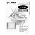 $4.99 21BFX1 SHARP
Owner's Manual Complete owner's manual in digital format. The manual will be available for download as PDF file aft…
|
|
|
> |
|