|
|
|
Categories
|
|
Information
|
|
Featured Product
|
|
|
 |
|
|
There are currently no product reviews.
 ;
Great service manua!
Always great value and fast service A++++++++++++++++++
;
Excellent Service manual, good quality scans, quick service and very good value. Well reccomended ! All good.
;
Great value service manual!
Good-quality scans. Detailed and valuable informations.
A+++++++++++++++
;
Great value service manual!
Good-quality scans. Detailed and valuable informations.
A+++++++++++++++
;
Excellent scan quality. A complete and very useful manual with all details.
Great service at low price A+++++++++++++++++
20D2-S/G 21D1-S/G 21D2-S/G
DESCRIPTION OF SCHEMATIC DIAGRAM
SAFETY NOTES:
1. DISCONNECT THE AC PLUG FROM THE AC OUTLET BEFORE REPLACING PARTS. 2. SEMICONDUCTOR HEAT SINKS SHOULD BE REGARDED AS POTENTIAL SHOCK HAZARDS WHEN THE CHASSIS IS OPERATING.
NOTES:
1. The unit of resistance "ohm" is omitted. (K = 1000 ohms, M = Mega ohm). 2. All resistors are 1/10 watt, unless otherwise noted. 3. All capacitors are µF, unless otherwise noted. (P = µµF).
IMPORTANT SAFETY NOTICE:
PARTS MARKED WITH " å " ( ) ARE IMPOTANT FOR MAINTAINING THE SAFETY OF THE SET. BE SURE TO REPLACE THESE PARTS WITH SPECIFIED ONES FOR MAINTAINING THE SAFETY AND PERFORMANCE OF THE SET.
VOLTAGE MEASUREMENT CONDITIONS:
1. Voltages in parenthesis measured with no signal. 2. Voltages without parenthesis measured with 3mV B & W or Colour signal. 3. All the voltages in each point are measured with VTVM.
SERVICE PRECAUTION:
THE AREA ENCLOSED BY THIS LINE ( �� - �� ) IS DIRECTLY CONNECTED WITH AC MAINS VOLTAGE. WHEN SERVICING THE AREA, CONNECT AN ISOLATING TRANSFORMER BETWEEN TV RECEIVER AND AC LINE TO ELIMINATE HAZARD OF ELECTRIC SHOCK.
WAVEFORM MEASUREMENT CONDITIONS:
1. The colour bar generator signal of 2.0V peak applied at of Base Video Buffer Amp. Q252. 2. Approximately 4V AGC bias .
31
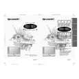 $4.99 21D2G SHARP
Owner's Manual Complete owner's manual in digital format. The manual will be available for download as PDF file aft…
|
|
|
> |
|