|
|
|
Categories
|
|
Information
|
|
Featured Product
|
|
|
 |
|
|
There are currently no product reviews.
 ;
Complete manual included schematics layouts and alignment procedure, clear to read and magnify, extremely pleased with manual and owner manual . com's service
;
perfect, i am very satisfait for the réception of the sansui r-5l service manual, thank you very much
;
Thank you, this is a rare document. Few others have it, but they charge way more for a download.
Great deal (even if you have to wait a few hours to get it).
;
The purchased manual is an high quality scan of the original Philips paper-based Service Manual. I am very satisfied!
 ;
The purchased manual is an scan of the original Panasonic paper-based Service Manual. Unfortunately the contrast is not perfect, but I am satisfied anyway!
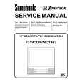
14R2MK2 21R2MK2
DESCRIPTION OF SCHEMATIC DIAGRAM
SAFETY NOTES:
1. DISCONNECT THE AC PLUG FROM THE AC OUTLET BEFORE REPLACING PARTS. 2. SEMICONDUCTOR HEAT SINKS SHOULD BE REGARDED AS POTENTIAL SHOCK HAZARDS WHEN THE CHASSIS IS OPERATING.
NOTES:
1. The unit of resistance "ohm" is omitted. (K = 1000 ohms, M = Mega ohm). 2. All resistors are 1/8 watt, unless otherwise noted. 3. All capacitors are µF, unless otherwise noted. (P = µµF).
IMPORTANT SAFETY NOTICE:
PARTS MARKED WITH " å " ( ) ARE IMPOTANT FOR MAINTAINING THE SAFETY OF THE SET. BE SURE TO REPLACE THESE PARTS WITH SPECIFIED ONES FOR MAINTAINING THE SAFETY AND PERFORMANCE OF THE SET.
VOLTAGE MEASUREMENT CONDITIONS:
1. Voltages in parenthesis measured with no signal. 2. Voltages without parenthesis measured with 3mV B & W or Colour signal. 3. All the voltages in each point are measured with VTVM.
SERVICE PRECAUTION:
THE AREA ENCLOSED BY THIS LINE ( �� - �� ) IS DIRECTLY CONNECTED WITH AC MAINS VOLTAGE. WHEN SERVICING THE AREA, CONNECT AN ISOLATING TRANSFORMER BETWEEN TV RECEIVER AND AC LINE TO ELIMINATE HAZARD OF ELECTRIC SHOCK.
WAVEFORM MEASUREMENT CONDITIONS:
1. The colour bar generator signal of 1.0V peak applied at pin (24) of IC201. 2. Approximately 4V AGC bias .
29
|
|
|
> |
|