|
|
|
Categories
|
|
Information
|
|
Featured Product
|
|
|
 |
|
|
There are currently no product reviews.
 ;
It was complete service manual with all needed service informations. Thanks.
 ;
El manual esta muy detallado, los numeros de partes y los esquemas de despiece son correctísimos y muy claros, tanto para los técnicos experimentados como para los novatos.
;
Ottima qualità grafica e completo nelle notizie. Costo abbastanza contenuto.
;
Great and quick support. The maual was exactly what I was looking for and my problem
solved. Many thanks.
;
Very good service Within one day i received a pdf of the users manual and electric circuits so I was able to measure the different voltages in the printed circuit and find out the fault Payment was also reliable and easy.Without the manual i could not have repaired.So thanks to "Search for a manual"
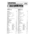
CONVERGENCE ADJUSTMENTS NOTE: Before attempting any convergence adjustments, the receiver should be operated for at least fifteen minutes. s CENTER CONVERGENCE ADJUSTMENT 1. Use the cross-dot pattern from among the built-in test signals. 2. Set the brightness and contrast for well defined pattern. 3. Adjust two tabs of the 4-Pole Magnets to change the angle between them (See figure 2.) and superimpose red and blue vertical lines in the center area of the picture screen. 4. Turn the both tabs at the same time keeping the angle constant to superimpose red and blue horizontal lines at the center of the screen. 5. Adjust two tabs of 6-Pole Magnets to superimpose red/ blue line and green one. Adjusting the angle affects the vertical lines and rotating both magnets affects the horizontal lines. 6. Repeat adjustments 3, 4, 5 keeping in mind red, green and blue movement, because 4-Pole Magnets and 6-Pole Magnets have mutual interaction and make dot movement complex.
6-POLE MAGNETS 4-POLE MAGNETS
s CIRCUMFERENCE CONVERGENCE ADJUSTMENT 1. Loosen the clamping screw of deflection yoke slightly to allow the yoke to tilt. 2. Temporarily put a wedge as shown in figure 1. (Do not remove cover paper on adhesive part of the wedge.) 3. Tilt front of the deflection yoke up or down to obtain better convergence in circumference. (See figure 3.) Push the mounted wedge into the space between picture tube and the yoke to fix the yoke temporarily. 4. Put other wedge into bottom space and remove the cover paper to stick. 5. Tilt front of the yoke right or left to obtain better convergence in circumference. (See figure 3.) 6. Keep the yoke position and put another wedge in either upper space. Remove cover paper and stick the wedge on picture tube to fix the yoke. 7. Detach the temporarily mounted wedge and put it in another upper space. Stick it on picture tube to fix the yoke. 8. After fixing three wedges, recheck overall convergence. Tighten the screw firmly to fix the yoke and check the yoke is firm. 9. Stick three adhesive tapes on wedges as shown in figure 1.
ADJUST THE ANGLE (VERTICAL LINES)
FIXED
ROTATE TWO TABS AT THE SAME TIME (HORIZONTAL LINES) PURITY MAGNETS CONVERGENCE MAGNET ASSEMBLY ADJUSTMENT OF MAGNETS
Figure 2.
BLU RED RED/BLU GRN
BLU RED
RED/BLU GRN
4-POLE MAGNETS MOVEMENT
6-POLE MAGNETS MOVEMENT
Center Convergence by Convergence Magnets
BGR R G B RGB INCLINE THE YOKE UP (OR DOWN) B G R
B G R
RGB
BGR
R G B
INCLINE THE YOKE RIGHT (OR LEFT)
Circumference Convergence by DEF Yoke
Figure 3. Dot Movement Pattern
�5�
SPECIFIC INFORMATIONS GENERAL ADJUSTMENTS
|
|
|
> |
|