|
|
|
Categories
|
|
Information
|
|
Featured Product
|
|
|
 |
|
|
There are currently no product reviews.
 ;
you are doing great job guys.....my father ask me to find out the schematics of Sony KV25R1D to sort out the problem ..(he was electrical technician, and excperianced with TV and simillar stuff). finally he found the cause and change all necessary parts....now he has got working old dog..and is very happy!!... thank you all.. NB..he also saved the repair cost.
 ;
Perfect. Received my manual within 24 hours. Clear scan of the manual I needed. No problem.
;
Item as described, very well detailed manual with complete schematics. I've received the download information shortly after payment, very good support.
;
Really good and well scanned. File is complete the full service manual for 5$
;
Good product and very helpfull to repair. Many thanks.
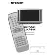
32KF-84H
Vertical Bow Adjust the Vertical Bow so that the picture is centred. The effect of this adjustment is shown in figure 11. � When the volume up button is pressed, the vertical bow changes to left. � When the volume down button is pressed, the vertical bow changes to right. � Press the stand-by button on the remote control to store. Vertical Amplitude Adjust the Vertical Amplitude so that 8% over-scan is achieved. The effect of this adjustment is shown in figure 12. � When the volume up button is pressed, the vertical size of the picture increases. � When the volume down button is pressed, the vertical size of the picture decreases. � Press the stand-by button on the remote control to store. S Correction Adjust the S Correction so that the picture symmetrical between the top, centre and bottom. The effect of this adjustment is shown in figure 13. � When the volume up button is pressed, the top and bottom scanning decreases and the centre scanning increases. � When the volume down button is pressed the top and bottom scanning increases and the centre scanning decreases. � Press the stand-by button on the remote control to store. Vertical Shift Adjust the Vertical Shift so that the picture is centred. The effect of this adjustment is shown in figure 14. � When the volume up button is pressed, the picture moves up. � When the volume down button is pressed, the picture moves down. � Press the stand-by button on the remote control to store. Figure 14
Colour Adjustments The following adjustments should only be carried out when the CRT, IC850, IC851 or IC852 are replaced. G2 and Cut Off Adjustments 1. Follow the procedure below to set the G2 1.1 Tune the set to the output of a signal generator (cross hatch pattern). 1.2 2. In the user menu, set the picture levels to the FACTORY settings (normalized). 1.3 Connect the oscilloscope to the RED cathode (pin 8 of CRT socket) and adjust G2 to read 150V on the sensor pulse as in the drawing: Note: Oscilloscope should be adjusted for vertical TV field trigger and synchronized with video signal.
Figure 11
Figure 12
Figure 13
150 V
CH1 gnd
Figure 15
10
|
|
|
> |
|