|
|
|
Categories
|
|
Information
|
|
Featured Product
|
|
|
 |
|
|
There are currently no product reviews.
 ;
This comprehesive service maual was greatly appreciated, as was the digital download.
 ;
Good en helpfull black and white scanned Srfvice manual of the Philps D8444. Quick service and delivery
;
Scan was really good quality, easy to read, download easy
;
very good manual as always. easy to read, detailed and includes schematic
;
I'm very satisfied with your manual service. Your website made it easy to locate the correct manual. Also the quality is great and I never had a problem reading the fine details.
Thanks again.
Jeff Miller
JM Electronics
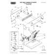
Mechanical Instructions
4.4.1 Top Control Assy/Panel
A02E
4.
EN 13
M
Top control board
1. Release the two fixation clamps (1) by pushing them upward. 2. At the same time, the complete assy must be pulled backward (2). 3. If the board has to be removed, release the two clamps at the sides of the bracket and lift panel out (3). 4.4.5 DAF Assy/Panel
CL 06532012_003.eps 030200
1 4 3 3
4
Figure 4-3 Top control panel 1. Remove the two fixation screws, which hold the panel. 2. Pull the board backward (w.o.w. release it from the front hinge). 3. The board can easily be lifted out of the bracket after releasing the two fixation clamps at the connector side. 4.4.2 Side I/O Assy and Panel Figure 4-6 DAF-module 1. Remove the fixation screw [1] (if present). 2. Push down the fixation clamp [2], and pull the complete bracket at the same time away from the CRT [3]. The module is now free from the LSP-bracket. 4.4.6 Small Signal Board (SSB)
2
CL 16532044_011.eps 241003
1
CL 06532012_004.eps 030200
1 3
Figure 4-4 Side-I/O panel 1. The complete Side I/O-assembly can easily be removed by unscrewing the two fixation screws. 2. The board can easily be lifted out of the bracket after releasing the two fixation clamps.
3
2 2
CL 06532153_002.eps 211103
Figure 4-7 SSB removal 4.4.3 4.4.4 Mains Switch Assy/Panel Accessing the Mains Switch/LED panel 1. Push the top of the SSB towards the LOT [1]. 2. Due to the pressure, the two metal clamps at both sides of the SIMM-connector will release [2]. 3. Take the complete SSB out [3]. 4.4.7 Large Signal Panel (LSP) 1. Remove the SSB (see paragraph �Small Signal Board (SSB)� above). 2. Disconnect the necessary cables. 3. Remove the fixation screw, which is located nearby the SIMM-connector. 4. Release the fixation clamps on the left of the LSP-bracket (the board hinges at the right side). 5. Remove the board from the bracket.
1 1
2
4.5
3 3
CL 06532012_005.eps 030200
Set Re-assembly
To re-assemble the whole set, do all processes in reverse order. Be sure that, before the rear cover is mounted: � � The mains cord is mounted correctly in its guiding brackets. All wires/cables are returned in their original positions. This is very important due to the large �hot� area of the set
Figure 4-5 Mains Switch/LED panel
|
|
|
> |
|