|
|
|
Categories
|
|
Information
|
|
Featured Product
|
|
|
 |
|
|
There are currently no product reviews.
 ;
This is the ONLY copy of this manual I could find for a realistic price. Even Panasonic could not provide me with one.
The PDF is a very good copy and it helped me diagnose and find the fault with the unit I have.
;
Very complete and well reading drawings. Documentation is essential for successful repairs.Good documentation, with all that is necessary. This manual was what I was waiting with all the information necessary for the repairing I need it for. You must buy it if you want to do repairs or simply understand how it works.
 ;
Excellent service manual includes everything is need to repair this radio-caseete, how to disassemble, wiring diagram, all , waiting time until the download was only a few hours. I'm going to buy service manuals from here, are cheap and very good.Thank you.
;
Good service manual,i saved from scrapping this deck,is now fully functional.Thanks.
;
Found this to be the manual included with the original packinging, was helpfull but did not give any detailed repair instructions.
EN 20
4.
EM5.1E
Mechanical Instructions
4.4.8 Large Signal Panel (LSP) 1. Remove the SSB (see paragraph 'Small Signal Board,SSB' above). 2. Remove the Auto-Scavem assy (see paragraph 'Auto Scavem Assy/Panel' above). 3. Disconnect the necessary cables. 4. Release the fixation clamps on the left of the LSP-bracket (the board hinges at the right side). 5. Remove the board from the bracket.
1. Release the two fixation clamps (rather difficult to reach), by pushing them upwards [1]. At the same time, pull the complete assy backwards [2]. Note: be aware that the degaussing coil can hamper this. 2. Release the two fixation clamps on the two sides of the bracket (the board hinges at the connector side). 3. Remove the board from the bracket. 4. When the light guide (sitting in the cabinet, in front of the LEDs) is defective, you can replace it by pushing it forwards at the left side (it hinges at the right side, seen from the rear). 4.4.4 DAF Assy/Panel
4.5
Set Re-assembly
To reassemble the whole set, do all processes in reverse order. Be sure that, before the rear cover is mounted: � The mains cord is mounted correctly in its guiding brackets. � All wires/cables are returned in their original positions. This is very important due to the large 'hot' area of the set
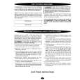
1 4 3 3
4
2
CL 16532044_011.eps 150501
Figure 4-11 DAF-module
1. Remove the fixation screw [1] (if present). 2. Push down the fixation clamp [2], and pull the complete bracket at the same time away from the CRT [3]. The module is now free from the LSP-bracket. 3. Release the fixation clamps [4], in order to remove the print from its bracket. 4.4.5 Double window, PIP panel (If present) 1. It is not necessary to remove the Double window bracket. 2. To remove he Double window PWB, release both upper clamps and take out the PWB. 4.4.6 Auto-SCAVEM Assy/Panel This panel is placed on the left side of the SSB (See figure 'Service Position 2'). Because most of its components are placed on the bottom side, you must lift the panel from its bracket before you can measure it. 1. Therefore, release the two fixation clamps at the top side. 2. Lift the panel from the bracket (it hinges at the bottom). To remove the bracket: 1. First, remove the panel from the bracket, as described above. 2. Then, remove the two fixation screws at the bottom. 3. Lift the Auto-Scavem bracket slightly up, and at the same time bend the top a little away from the tuner. 4. Now, push the bracket into the direction of the CRT, and lift it out of the LSP-bracket. 4.4.7 Small Signal Board (SSB) See paragraph 'Small Signal Board (SSB)' above.
|
|
|
> |
|