|
|
|
Categories
|
|
Information
|
|
Featured Product
|
|
|
 |
|
- Technical Specifications, Precautions
- Disassembly
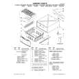
- Layout of Main Mechanical Parts
- Periodic Maintenance
- Key to Abbreviation
- Mechanism Control Block Diagram
- Audio Block Diagram Type B, C, D
- Drum Servo Block Diagram
- Capstan Servo Block Diagram
- Audio Block Diagram Type A
- Audio Demodulator Block Diagram Type A
- Luminance Signal Block Diagram
- Color Signal Block Diagram
- Tuner/IF Block Diagram Type A, B
- Timer/Presetter Block Diagram Type A, B
- Tuner/IF Block Diagram Type C, D
- Timer/Presetter Block Diagram Type C, D
- Overall Wiring Diagram Type A
- Overall Wiring Diagram Type B
- Overall Wiring Diagram Type C
- Mechacon, Servo, Audio and Operation Circuits Type A
- A/S/M Circuit Board Type A
- Operation Circuit Board Type A
- Mechacon Sub Board
- Mechacon, Servo, Audio and Operation Circuits Type B, C, D
- A/S/M Circuit Board Type B, C, D
- Operation Circuit Board Type B, C, D
- Mechacon Sub Board
- Video Circuits
- Video Circuit Board Type A
- Video Circuit Board Type B, C, D
- Terminals
- Audio and Demodulator Circuits Type A
- Audio Circuit Board
- Demodulator Circuit Board
- Tuner/IF Circuit Type A
- Regulator Circuit
- Timer/Presetter Circuit Type A, B
- Tuner/IF Circuit Board Type A
- Timer Sub Board Type A, B
- Timer/Presetter Circuit Board Type A, B
- Regulator Circuit Board
- Tuner/IF and Timer/Presetter Circuits Type C, D
- Tuner/IF Circuit Board Type C, D
- Timer/Presetter Circuit Board Type C, D
- Tuner/IF Circuit Type B
- Tuner/IF Circuit Board Type B
- Mix Booster
- Remote Control Circuit
- RF - Converter Circuits
- 2. General Mechanical Adjustment
- 2.1 Important Precautions
- 2.1.2 Required Jigs and Tools
- 2.2 Layout of Main Mechanical Parts
- 2.2.1 Exploded View
- 2.3 Main Assembly Replacements
- 2.4 Tape Transport System Checks and Adjustment
- 2.5 Interchangeability Adjustment
- 3. Electrical Adjustments
- 3.1 Preparation
- 3.2 Regulator Circuit
- 3.3 Servo Circuit
- 3.4 Mechacon Circuit
- 3.5 Video Circuit
- 3.6 Audio Circuit Stereo
- 3.6 Audio Circuit Mono
- 3.7 Tuner/IF Circuit
- 3.8 Demodulator Circuit (Stereo)
- 4. Audio Multiplex TV Signal Generator
- 5. Position of Testpoints and Adjusters
- General Description
- Mechacon Functions in Various Modes
- OPERATE Switch ON
- Cassette Housing up and down States
- Operating Modes
- Timer Switch ON
- Mode Shift Table
- Timer Functions and Operation
- Clock
- Programm Functions
- Timer Recording Operation
- Program Entry Complete
- Setting Corrections and Checks
- Mode Return
- Instant Recording
- Counter
- Counter Reset
- Zero Output
- Lap Time
- Lap Time Release
- Lap Time Reset
- Tape Running Indicator
- Station Selection Typ C, D
- Station Selection Typ A, B
- Mechanism Description
- Functions of Major Parts
- Drum Motor
- Solenoid
- Capstan Motor
- Mode Control Motor
- Description of Operations
- Stop Mode
- Loading Mode
- Play Mode
- Still Mode
- Search Mode
- Pause Mods
- Unloading Mode
- Fast Forward/Rewind Modes
- Cassette Housing Operation
- Cassette Loading Mechanism
- Cassette Loading and Eject End Detect
- Upper and Lower Door Mechanisms
- Circuit Description
- Mechanism Control System
- General
- Infrared Remote Control Unit
- Mechanism Features
- Circuit Description
- Servo System
- General
- Principle of the Servo System
- Servo Circuit Description
- Video System
- General
- Luminance Signal System
- Color Signal System
- Audio System
- General Typ B, C, D
- Block Diagram Description
- Muting Control
- General Stereo Version Typ A
- Block Diagram Description
- Demodulator Circuit Stereo Version Typ A
- Timer Presetting Circuit
- Recorder Typ C, D
- Clock
- Program Functions
- Timer Recording Operation
- Program Entry Complete
- Setting Corrections and Checks
- Mode Return
- Instant Recording
- Counter
- Counter Reset
- Zero Output
- Lap Time
- Lap Time Release
- Lap Time Reset
- Tape Running Indicator
- Station Selection
- Typ A, B
- Auto Tuning Operation
- Pulse - Width Modulation (PWM)
- Functions of Major ICs
There are currently no product reviews.
 ;
Print was clear and easy to read. Thank you Joe joeoldaudio
;
Very great deal. In a few minutes a have the manual, that I needed. Thanl you very much
;
Manual was complete. Received it quickly. No problems
;
Product was very good. Received quickly and complete
 ;
The Sony AV-3600 service manual was what I needed for the repair of this unit
Thanks for the good service
Dave
|
|
|
> |
|