|
|
|
Categories
|
|
Information
|
|
Featured Product
|
|
|
 |
|
|
There are currently no product reviews.
 ;
This was precisely what I was looking for. Complete and good quality!
 ;
This is the ONLY copy of this manual I could find for a realistic price. Even Panasonic could not provide me with one.
The PDF is a very good copy and it helped me diagnose and find the fault with the unit I have.
;
Very complete and well reading drawings. Documentation is essential for successful repairs.Good documentation, with all that is necessary. This manual was what I was waiting with all the information necessary for the repairing I need it for. You must buy it if you want to do repairs or simply understand how it works.
;
Excellent service manual includes everything is need to repair this radio-caseete, how to disassemble, wiring diagram, all , waiting time until the download was only a few hours. I'm going to buy service manuals from here, are cheap and very good.Thank you.
;
Good service manual,i saved from scrapping this deck,is now fully functional.Thanks.
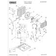
WARNING: BEFORE SERVICING THIS CHASSIS, READ THE "X-RAY RADIATION PRECAUTION", "SAFETY PRECAUTION" AND "PRODUCT SAFETY NOTICE" ON PAGE 3 OF THIS MANUAL.
PICTURE TUBE COMPONENTS ADJUSTMENT
ADJUSTING PROCEDURE IN REPLACING CRT Cutoff Lens focus Electrical focus RGB FOCUS ADJUSTMENT User convergence center check 1. Call-up the adjustment mode (see page 10) 2. Press a button on the remote controller in order to display Centering (PAL) the internally-generated cross-hatch (See TEST SIGNAL SELECTION on page 11.) Convergence adjustment 3. Expose only RED by covering the GREEN and BLUE (PAL/NTSC) lenses with caps. 4. Loosen the RED lens fixing screws (refer to Fig. a), and White balance adjust the RED lens focus to obtain the sharpest point while observing the middle and peripheral sections of the Sub bright adjustment screen. End DESCRIPTION OF NECK COMPONENTS 2 1 Fig. a 5. Use the focus VR of �R� of the focus pack in order to adjust the electric focus in the middle and peripheral sections of the screen to its sharpest level. 6. Check the RED focus of the whole screen and if necessary repeat steps 4 and 5. 7. Fix the RED lens by tightening its fixing screws. 8. Expose only GREEN by covering the RED and BLUE lenses with caps. 9. Display the internally-generated cross-hatch signal. 10. Adjust the GREEN lens focus on the left border of the screen to its sharpest level, then check the focus on the right border, and if it is at its sharpest level, fix it in that position by tightening the lens screws. (1) If the horizontal line toward the right border is redflared, turn the lens screw slightly right in order to balance it with the left border. (After adjustment, the left border tends to be slightly green-flared, and the right border tends to be slightly red-flared.) (2) If the horizontal line toward the right border is greenflared, turn the lens screw slightly left in order to balance it with the left border. (After adjustment, the left border tends to be slightly red-flared, and the right border tends to be slightly green-flared.) Note: The aim of the above-described adjustment procedure for the Green lens focus is to obtain the best lens focus after 2 - 3 hours of warming up taking into account the focus drift; it applies if the warming up time before the adjustment is less than 30 minutes. (The horizontal line in the screen middle section tends to be slightly redflared.) �6�
Yoke horizontal
SPECIFIC INFORMATIONS GENERAL ADJUSTMENTS
S.V.M. COIL
1 Deflection yoke and convergence yoke. The position on the neck is required most front (CRT funnel side) and the screw is fastened after rotating yoke adjusting picture tilt. 2 Centering magnet After adjusting picture tilt, picture position is finally fixed by this magnet. In order to get maximum margin of user convergence control for center of screen, this magnet have to be used for center convergence adjustment. PREPARATION Operate the receiver for at least 5 minutes. R, G, B CUTOFF (SCREEN VR) ADJUSTMENT 1. Adjust before replace the screen assembly. 2. Set user control to reset position. CONTRAST � Max BRIGHTNESS, COLOR, TINT � Center.
(
)
3. Call up the adjustment mode display, then select the item RCUT. 4. Adjust the data of items RCUT, GCUT, and BCUT to "40H". 5. Press the -/-- button on Remote. (Y-MUTE : ON) 6. Gradually rotate R, G and B screen volume of FOCUS PAC clockwise or counterclockwise until the raster appears slightly on the CRT through the each lens, and leave them. (Lookin to the lens in order to check the raster.) 7. Press the -/-- button on Remote. (Return to Normal Picture)
|
|
|
> |
|