|
|
|
Categories
|
|
Information
|
|
Featured Product
|
|
|
 |
|
|
There are currently no product reviews.
 ;
We received the manual in a timely manner and it was exactly what we were expecting.
;
Excellant, finally this is want I need and searching for The service manual is fantastic and thank you to owner-manuals.com and its service. Price is reasonable. It's a bit slow on my end in downloading but manage to receive the whole manual without a break. once again, thanks.
;
Very good scanning quality. All schematics are very legible. Worth every cent !
;
Excellent quality, very quick download turnaround, will definately use again.
 ;
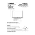
This is a awesome quality scan of the original Service Manual for Technics 8099.
Contains the circuit diagram, PCB layout, adjust/tune instructions as well.
Since this is my first buy here, i'm really glad! This site do works as intended/described, it's definitely not scam!
Мои рекомендации! Все мануалы настоящие!
8. Re-Adjustment
A���� changing the Panel Module, re-adjustment is needed according to the item 8.1.to 8.5. For Power Unit, item 8.1; for Signal Board, item 8.2 to 8.5* and for Video Board, item 8.2, 8.4,8.5 are needed. It is recommended to start re-adjustment after 30 minutes warm-up with the Burn-in signal.
*) When it is not inserted into VIDEO Unit of optional Board in Signal Board replacement, VIDEO Unit becomes necessary. In this case, insert the dummies' VIDEO unit and execute the above adjustment item.
How to set to Burn-in signal (red, green, blue, white, yellow, cyan, magenta, black signal) Turn off the sub power button (or power button on the Remote Controller), then turn on the SUB POWER button for more than 5 seconds while you keep pushing VOLUME� and RECALL buttons located on the bottom of the set.
When you fall out from Burn-in mode, turn off the sub power button (or power button on the Remote Controller),then turn on the SUB POWER button for more than 5 seconds while you Keep pushing VOLUME� button located on the bottom of the set.
8.1 Vs and Va voltage adjustment on Power Unit
Power Unit PIN502 GND PIN501 Vs VR51Vs ADJ.(IC591) PIN301 Va VR51 Va ADJ.(IC391)
How to prepare 1.Connect the DC Voltmeter to the Vs test point and the GND point (or the Va test point and the GND point) on the Power Unit. 2.Connect VGA (75), no-setup, and all black signal to RGB input terminal. 3.Check the amount of Vs and Va voltages printed on the label located lower left side on the Panel Module. How to adjust 1.If the difference of the printed voltage of Vs and the value of DC Voltmeter of Vs is over ±0. 4 V, adjust the Vs ADJ Volume located upward on the Power Unit to within ±0. 4 V. 2. If the difference of the printed voltage of Va and the value of DC Voltmeter of Va is over ±0. 4 V, adjust the Va ADJ Volume located upward on the Power Unit to within ±0. 4 V.
Y-sus
Power Unit
X-sus
Label
Panel Module
Rear View
18
|
|
|
> |
|