|
|
|
Categories
|
|
Information
|
|
Featured Product
|
|
|
 |
|
|
There are currently no product reviews.
 ;
This Service manual is very well scanned and its clean to read, no any anti-theft words that un-english could understand. I got my CCD600 working with this manual and it´s clear shematics :)
;
I was very pleased with the service provided and was surprised at how good the quality was of the manual. I thought it may be a third generation copy or so, but it is as good as the websites that charge 3 times this much. I repair some electronics for family and friends without charge, so this is perfect for me. Thank you very much.
;
The service was great and the document was also great. Highly recommend!!!!
If anyone has a users manual... Please email me. need one. $ [email protected]
;
I needed a service manual as the display on my oscilloscope was very dim. I thought I'd give owner-manuals.com a try, as they advertised a huge number of manuals. Sure enough they had one listed. I bought it hoping it would be useful... actually, I bought it hoping it would be readable! I've had manuals from online sources in the past, and been very disappointed. Not this time! An excellent manual, complete, and very readable. Using it I fixed my 'scope, and as such the manual was an investment that paid off manyfold. Do I have any complaints? One very minor one - The circuit diagrams could have been scanned at a higher resolution, as some of the details were a little difficult to make out - not impossible, just not as easy as my old eyes would like! Overall, I'm very satisfied with my manual, and I will certainly be using this company again. Well done.
 ;
I Have looked for this manual for quiet a while now, I have finally found it here. I believe this is the only place they have them in a very nice scan, pages are very clear to read, some of the pages are a bit tilted but overall it is great to have this manual available for purchase. Thanks
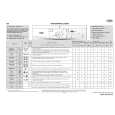
Note:
Connect a probe (10: 1) of the oscilloscope test point for adjustment. Connect ground ( ) terminal of oscilloscope probe to TP3 (VREF) for all adjustment.
2. Tracking Balance Check
Oscilloscope (DC range)
1. Focus Bias Adjustment Make the focus bias adjustment when replacing and repairing the optical block.
Oscilloscope (DC range)
TP1 (TE) TP3 (VREF)
+ �
TP2 (RF) TP3 (VREF)
+ �
1) Connect an oscilloscope to test points TP1 (TE) and TP3 (VREF). 2) Start up the CD test mode. 3) Insert the test disc TCD-782 (YEDS-18) and enter the traverse mode of the CD test mode. 4) Confirm that the traverse waveform on an oscilloscope is vertically symmetrical as shown in the figure below. 5) After confirming the waveform, release the CD test mode.
1) Connect an oscilloscope to test points TP2 (RF) and TP3 (VREF). 2) Turn on the power switch. 3) Insert test disc TCD-782 (YEDS-18) and play back the second program. 4) Adjust SFR101 so that RF signal of the test point TP2 (RF) is MAX and CLEARREST.
A VREF B A=B
MAX 1.4 ± 0.1 Vp-p 0V EYE PATTERN must be CLEAR and MAX
VOLT/DIV: 20mV TIME/DIV: 1mS
VOLT/DIV: 0.5V TIME/DIV: 0.5µS Note: The current of the laser signal can be checked with the voltages on both sides of R46 (voltage across 10�). The difference for the specified value shown on the label must be within ± 6.0mA.
KSS-213B 15165 SG442
44.2mA
Laser current Iop =
Voltage across R46 10�
20
|
|
|
> |
|