|
|
|
Categories
|
|
Information
|
|
Featured Product
|
|
|
 |
|
|
There are currently no product reviews.
 ;
Excellent transaction - clean document received - Thanks a lot
;
Manual is in German but complete. I needed this one to fix a long lasting problem with the internal PSU of the camera. Most of the capacitors begin to leak after a few years wich results in the inability to power on the camera. When you try to turn it on the power led flickers and the unit directly turns off. Thanks to this manual I was able to locate all bad cap's and to dis- and reassemble the camera without any problems.
 ;
We received the manual in a timely manner and it was exactly what we were expecting.
;
Excellant, finally this is want I need and searching for The service manual is fantastic and thank you to owner-manuals.com and its service. Price is reasonable. It's a bit slow on my end in downloading but manage to receive the whole manual without a break. once again, thanks.
;
Very good scanning quality. All schematics are very legible. Worth every cent !
LC37/LC37F
SAFETY PRECAUTIONS
NOTICE: Comply with all cautions and safety-related notes located on or inside the cabinet and on the chassis or optic unit. WARNING: Since the chassis of this receiver is connected to one side of the AC power supply during operation, whenever the receiver is plugged in service should not be attempted by anyone unfamiliar with the precautions necessary when working on this type of receiver. The following precautions should be observed: 1. Do not install, remove, or handle the optic unit in any manner unless shatterproof goggles are worn. People not so equipped should be kept away from the optic unit while handling. 2. When service is required, an isolation transformer should be inserted between power line and the receiver before any service is performed on a �HOT� chassis receiver. 3. When replacing a chassis in the receiver, all the protective devices must be put back in place, such as barriers, nonmetallic knobs, adjustment and compartment cover-shields, isolation resistors, capacitors, etc. 4. When service is required, observe the original lead dress. 5. Always use the manufacturer�s replacement components. Critical components as indicated on the circuit diagram should not be replaced by another manufacturer�s. Furthermore, where a short circuit has occurred, replace those components that indicate evidence of overheating.
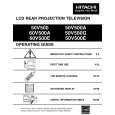
Leakage Current Hot Check Plug the AC line cord directly into a 120V AC 60Hz outlet (do not use an isolated transformer for this check). Turn the AC power ON. Using a Leakage Current Tester (Simpson�s Model 228 or equivalent), measure for current from all exposed metal parts of the cabinet (antennas, screwheads, overlays, control shafts, etc.) particularly any exposed metal part having a return path to the chassis or to a known earth ground (water pipe, conduit, etc.). Any current measured must not exceed 0.5 MIU.
DEVICE UNDER TEST TEST ALL EXPOSED METAL SURFACES 2-WIRE CORD
LEAKAGE CURRENT TESTER
(READING (READING SHOULD NOT SHOULD NOT BE ABOVE ABOVE 0.5 MIU) 0.5 mA)
+
-
EARTH GROUND
ALSO TEST WITH PLUG REVERSED (USING AC ADAPTER PLUS AS REQUIRED)
AC LEAKAGE TEST 6. Before returning a serviced receiver to the customer, the service technician must thoroughly test the unit to be certain that it is completely safe to operate without danger of electrical shock, and be sure that no protective device built into the receiver by the manufacturer has become defective, or inadvertently defeated during servicing. Therefore, the following checks should be performed for the continued protection of the customer and service technician. Leakage Current Cold Check With the AC plug removed from the 120V AC 60Hz source, place a jumper across the two plug prongs. Using an insulation tester (DC500V), connect one lead to the jumpered AC plug and touch the other lead to each exposed metal part (antennas, screwheads, metal overlays, control shafts, etc.), particularly any exposed metal part having a return path to the chassis should have a minimum resistor reading of 2.4M and a maximum resistor reading of 5.2M . Any resistance value below or above this range indicates an abnormality which requires corrective action. An exposed metal part having a return path to the chassis will indicate an open circuit. ANY MEASUREMENTS NOT WITHIN THE LIMITS OUTLINED ABOVE ARE INDICATIVE OF A POTENTIAL SHOCK HAZARD AND MUST BE CORRECTED BEFORE RETURNING THE RECEIVER TO THE CUSTOMER.
2
TABLE OF CONTENTS
|
|
|
> |
|