|
|
|
Categories
|
|
Information
|
|
Featured Product
|
|
|
 |
|
|
There are currently no product reviews.
 ;
Perfect quality, highly appreciated service !!!
Fast delivery of the download info, no issues at all. Recommended E-manual shop !!!
;
hi owners manual- crew,
i am very satisfied about the trade with you.
if i need some other manuals, i will contact you again.
thanks
frank kappler
;
Full Panasonic service Manual, as described, no problems
;
This place is amazing. Got our manual in a few hours. Print quality is excellent. Even the manufacturer didn't have this manual. The price was excellent. How many more stars can I give them? More than satisfied.
;
This was a very hard to find manual. The unit is long discontinued and Pioneer doesn't retain every manual for every model. Thanks owner's-manual.com!
SERVICE INSTRUCTIONS
For radios that require an open circuit when the microphone is on-hook (such as many Ericsson/GE models), the hang-up logic can be reversed by the following procedure. 1. Open the microphone case by removing three retaining screws. 2. Carefully separate the case halves, taking care not to lose the rubber pieces associated with the cartridge assembly.
3. Add the following components to the PC board assembly at the locations indicated by the highlighted parts in the dash-line parts in Figure 5 and photo in Figure 6.
� �
NPN Transistor Q2 (Shure Part No. 86A350; Motorola 2N5210) Resistor R5, 56 k�, 1/4 W (Shure Part No. 45LA563C)
4. Unsolder and move the blue wire from W5 to W4.
W4 HANG-UP BUTTON BLU
W8
W5
JUMPER (INSTALLED)
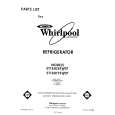
SP2 86A434 J1 W3 C1 WHT R1 10K W2 CARTRIDGE .018µF SP1 86B434R W1 GND R4 470 C8 + 10µF YEL W6 BLK W7 C5 .001µF C6 120pF R3 27K R6 51 C4 .001µF C3 120pF 1 86A350 C7 120pF C2 .001µF R2 68K 3 2 1 2 3 4 5 6 Q1 AUDIO OUT/DC BIAS PTT HI HANGUP PTT LO N/C GND
CIRCUIT DIAGRAM FIGURE 5
3
|
|
|
> |
|