|
|
|
Categories
|
|
Information
|
|
Featured Product
|
|
|
 |
|
|
There are currently no product reviews.
 ;
Excellent quality service manual. Quick processing, fair prices. Love to do business again. Thank you!!!
;
Excellent service manual, the only known point of note is the alignment of improvability scanned pages within the pdf page. The resolution is good.
;
I was very glad recieving the service manal from You. Additionaly very fast. Extremaly nice servicing. Thanks very mach! Now my GX-220 working better, than it was made. Alexander from Moscow, Russia/
;
Sweet! I won the item on eBay and couldn't adjust the geometry or even keep a steady picure. This guide has the full schematics (not available anywhere else as far as I could tell), and was a bargain for the wealth of knowledge it contains. I hooked it up to my testing equipment, tweaked a few potentiometers and got it playing videogames in no time. Thanks!
;
It was just what I need to fix my old BMW's CD player. Very convenient also. Thank you.
CCS Technical Documentation
RH-12/RH-28 Car Installation Kit
1.
2.
3.
4.
HF Microphone HFM-8
The HF microphone should be installed according to the directions in the separate microphone installation guide. Ensure the microphone is as close to the driver�s mouth as possible, and attached to a surface that is mechanically quiet. The microphone should be mounted at least 3 ft./1 m away from the handsfree unit speaker to avoid acoustic feedback. Insert the HFM-8 plug into the MIC socket in HFW-1 and twist 90° clockwise to lock firmly in place.
HF Speaker HFS-12
Install the HF speaker so that it is at least 3 ft./1 m away from the HFM-8 microphone to avoid acoustic feedback. Insert the HFS-12 plug into the SPEAKER socket and twist 90° clockwise to lock firmly in place. Under no circumstances should the HFS-12 prevent the driver from controlling or operating the vehicle in any way or observing traffic.
Power Cable PCU-4
The power cable connects the wireless handsfree unit HFW-1 to the vehicle�s power supply (DC socket). The red wire must be connected to the + voltage on the vehicle�s power supply via the supplied fused connector. The black wire must be attached to a good negative GND connection. The blue ignition sense (IGNS) wire is connected to +12 V voltage con trolled by the vehicle�s ignition key via the supplied fused connector. See section "Ignition Sense". The yellow wire is used for car radio muting (CRM). The line goes down to 0 volts during a call. See section "Car Radio Muting".
Issue 1 02/04
Nokia Corporation
Page 19
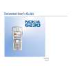 $4.99 6230 NOKIA
User Guide It's a complete guide ( also known as operating manual or owner's manual), and it's in PDF format. A…
|
|
|
> |
|