|
|
|
Categories
|
|
Information
|
|
Featured Product
|
|
|
 |
|
|
There are currently no product reviews.
 ;
Exactly the JVC service manual and schematics that I was looking for - delivered just hours after order. Will do business again!
;
This is a fantastic site, ad I have been a returning satisfied cusumer!
Thanx for a great sevice!
;
Je suis audiophile belge, électronicien et créateur d'enceintes acoustiques.
J'ai apprécié la qualité des documents fournis. Ils sont très lisibles, ils peuvent être agrandis sans problème et ils sont complets. Pour moi, c'est parfait. Pour cette qualité, je suis d'accord de payer. Et le système de paiement et d'envoi est simple. Merci, continuez comme cela.
Frédéric
;
The cover page was a little scary, very dark but readable. The remainder of the document was better copy and easily readable. Why would I give 5 Stars? (1) PRICE, (2) AUTHENTICITY, It was the real deal, filled with service information, including the specific information I required. (3) PRIVACY, I didn't start to get slammed with spam. (4) EASY TRANSACTION. Painless. (5) COMPLETE, I have found several manuals here, that I could find nowhere else. (6) I will be a repeat customer!
;
Well done!!! I found what I need to have, indeed!
Furthermore, due to my hobby is repairing vintage equipments, I added this web site in my desk toolbar because I have in mind to search further service manuals. Thanks a lot www.owner-manuals.com !
Regards, Maurizio
of the countries in which they are to be sold. However, in order to maintain such compliance, it is equally important to implement the following precautions when a set is being serviced.
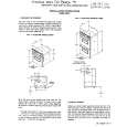
3) Align the lengths of the wires to be connected. Insert the wires fully into the connector. 4) Use the crimping tool to crimp the metal sleeve at the center position. Be sure to crimp fully to the complete closure of the tool. L. When connecting or disconnecting the internal connectors, first, disconnect the AC plug from the AC supply outlet.
Precautions during Servicing
A. Parts identified by the # symbol are critical for safety. Replace only with part number specified. B. In addition to safety, other parts and assemblies are specified for conformance with regulations applying to spurious radiation. These must also be replaced only with specified replacements. Examples: RF converters, RF cables, noise blocking capacitors, and noise blocking filters, etc. C. Use specified internal wiring. Note especially: 1) Wires covered with PVC tubing 2) Double insulated wires 3) High voltage leads D. Use specified insulating materials for hazardous live parts. Note especially: 1) Insulation Tape 2) PVC tubing 3) Spacers 4) Insulators for transistors. E. When replacing AC primary side components (transformers, power cord, etc.), wrap ends of wires securely about the terminals before soldering. F. Observe that the wires do not contact heat producing parts (heat sinks, oxide metal film resistors, fusible resistors, etc.) G. Check that replaced wires do not contact sharp edged or pointed parts. H. When a power cord has been replaced, check that 5~6 kg of force in any direction will not loosen it. I. Also check areas surrounding repaired locations. J. Use care that foreign objects (screws, solder droplets, etc.) do not remain inside the set. K. Crimp type wire connector The power transformer uses crimp type connectors which connect the power cord and the primary side of the transformer. When replacing the transformer, follow these steps carefully and precisely to prevent shock hazards. Replacement procedure 1) Remove the old connector by cutting the wires at a point close to the connector. Important: Do not re-use a connector (discard it). 2) Strip about 15 mm of the insulation from the ends of the wires. If the wires are stranded, twist the strands to avoid frayed conductors.
2-3
TVN_ISP
|
|
|
> |
|