|
|
|
Categories
|
|
Information
|
|
Featured Product
|
|
|
 |
|
|
There are currently no product reviews.
 ;
- Very good scan quality, PERFECT!
- Sehr gute scan Qualitaet, empfehlenswert!
Wolfgang Sundhaus
 ;
Good site, works ok and you get what you order, no problems experienced, got my manual within a day. A++++
;
Original well scanned manual. Got the job done. Microwave problem found & corrected. For $5 and a new magnitron from ebay, it was a cheap and good the first shot fix. Electrical schematics allowed me to mage sure every thing else was ok before cutting and order for parts. Hard to live without.
;
I was very skeptical of this website, I have never downloaded manuals before. I put it on the AMEX and payed through Paypal to ensure protection. I got the manual exactly as described and now I can replace the filter capacitor for this amp. Great Price, others selling for 12.99 or more and this is the same manual. I will search out this website for other manuals. Thank you
;
Manual was reasonably easy to follow. I am not an engineer or know much about electronics but with the manuals help I was able to figure out the problem, identify the part required for the repair. Replacement part cost around $30. Whilst replacing the part I was telling myself, "this aint gonna work cos it seems far too easy". Took about 15 minutes to do and my plasma TV works a treat. Would never have been able to do this without the service manual.
D
FM Abgleich
GB
FM Alignment
Bitte achten Sie darauf, da� die Stationstasten vor dem Abgleich mit bestimmten Frequenzen belegt werden müssen (siehe Seite 5).
Please observe that the station preset push-buttons have to be programmed to specified frequencies before the parameter programming (see page 5).
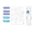
FM Phasenschieber - Abgleich
Künstliche Antenne (8 627 105 356) verwenden. Betriebsart ................................ FM Stationstaste ............................ 1 (97,2 MHz) Me�punkt ................................. MP 153 (X12/7) Abgleichelement ...................... Z 152 Spezifikation ............................. H>L Sprung Me�instrument ......................... Oszilloskop Signalquelle ............................. Me�sender f = 97,2 MHz, fmod = 1 kHz Hub = 22,5 kHz Signaleingang .......................... E' = 40 dBµV (+Bedämpfung!) 1. Klemmen Sie das Oszilloskop an MP 153 und Masse an. Schalten Sie den Oszilloskopeingang auf DC. 2. Stellen Sie den Me�sender auf 97,2 MHz, mit 22,5 kHz Hub und 1 kHz Modulation ein. 3. Speisen Sie das HF-Signal E' = 40 dBµV in die Antennenbuchse ein (Dämpfung der künstlichen Antenne beachten). 4. Drücken Sie die Stationstaste 1 (97,2 MHz). 5. Verstimmen Sie den Me�sender mit 1 kHz-Schritten um die halbe SL-Stop-Fensterbreite, d.h. auf 97,170 oder 97,230 MHz (siehe Skizze). Zwischen 29 kHz und 31 kHz von der Fenstermitte (97,200 MHz) sollte der oszillierende H>L Sprung an MP 153 erfolgen. Erfolgt der H>L Sprung nicht, geben Sie die halbe SL-StopFensterbreite von 30 kHz am Me�sender vor (97,170 oder 97,230 MHz), und stellen Sie den H>L Sprung mit Z 152 an MP 153 ein. 6. �berprüfen Sie abschlie�end die Fenstersymmetrie und korrigieren Sie die Einstellung von Z 152 ggf. erneut.
FM phase-shifter alignment
Use the dummy antenna (8 627 105 356). Operating mode ....................... FM Preset button ............................ 1 (97.2 MHz) Measuring point ....................... MP 153 (X12/7) Alignment element ................... Z 152 Specification ............................. H>L change Measuring instrument .............. oscilloscope Signal source ........................... signal generator f = 97.2 MHz, fmod = 1 kHz deviation = 22.5 kHz Signal input .............................. E' = 40 dBµV (+attenuation!) 1. Connect the oscilloscope to MP 153 and ground. Set the oscilloscope input to dc. 2. Adjust the signal generator to 97.2 MHz, 22.5 kHz deviation with the modulation of 1 kHz. 3. Feed the RF signal E' = 40 dBµV into the antenna input (observe the attenuation of the dummy antenna). 4. Press preset push-button 1 (97.2 MHz). 5. Detune the signal generator with steps of 1 kHz by half the width of the search tuning stop window, i.e. to 97.230 or 97.170 MHz (see sketch). The oscillating H>L level change at MP 153 should appear at about 29 to 31 kHz off the channel centre (97.200 MHz). If this is found to be different, tune to an offset of 30 kHz (97.170 or 97.230 MHz) and use Z 152 to adjust the H>L change at MP 153. 6. Finally check both slopes with regard of the window centre and make a correction if necessary.
Beispiel:
funterer H>L Sprung + foberer H>L Sprung 2 = fFenstermitte
Example:
funterer H>L level + foberer H>L level = fwindow centre 2
97,170
+ 2
97,230 = 97,200
97,170
+ 2
97,230 = 97,200
Die Abweichung von der Fenstermitte (97,200 MHz) darf bis zu ± 2 kHz betragen.
The permissible unbalance of the centre is 97.200 MHz ± 2 kHz.
97,170 MHz
97,200 MHz
97,230 MHz
5 Volt
0 Volt
60 kHz
97,169 MHz
� Im Anschlu� an diesen Abgleich müssen die DX/LO Programmierungen für FM und die RDS Grundempfindlichkeit neu programmiert werden (siehe Seite 11 + 12). - 16 �
97,231 MHz
At the end of this alignment DX/LO programming for FM and RDS - basic sensitivity must be redone. (see page 11 + 12).
|
|
|
> |
|