|
|
|
Categories
|
|
Information
|
|
Featured Product
|
|
|
 |
|
|
There are currently no product reviews.
 ;
We received the manual in a timely manner and it was exactly what we were expecting. Excellent replacement for original Service Manual.
All schematics are very legible. We are really satisfied.
;
We received the manual in a timely manner and it was exactly what we were expecting. Excellent replacement for original Service Manual.
All schematics are very legible. We are really satisfied.
;
Fast delivery and good quality manual.
Very easily downloadable from a given url.
Will be pleased to buy again from this seller.
;
Ottimo manuale, grafica ferfetta invio rapidissimo. Altissimo livello!!!!!
;
Great PDF easy to read good info needed for replacment of belts and assembly and specs.
Operating Instructions-7D15 MODES OF OPERATION Manual Stop Watch This mode uses the GATE ON OFF switches to manually turn the counter main gate on and off . The counting rate is determined by the CLOCK switches . Times of up to 10 5 s can be measured in this mode . Event Counter In the EVENTS mode, the 7D15 counters accept information from the B Input connector. The B TRIGGER 1 controls select the counter triggering point. From to . 108 events can be counted in this mode Frequency Measurements The 7D15 can measure frequencies directly from do to 225 MHz when used in the FREQ mode . To obtain greater resolution of low-frequency measurements, measure the period of the waveform and calculate frequency (Frequency = 1/Period). Frequency Ratio Measurements The ratio of one signal to another can be compared with a range of up to 104 :1 and, depending on the range, a resolution of up to 10-7 . In the Frequency Ratio mode, the "standard" or reference signal is usually connected to the EXT CLOCK IN and the signal to be compared is connected to the B Input connector.
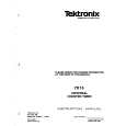
-PERIOD-~ PERIOD PERIOD AVERAGED (X10) B. PERIOD AVERAGED
Time Interval Measurements (TIM) Two basic modes of time interval measurements can be selected, TIM WIDTH, and TIM A-B . The TIM WIDTH mode measures the time between two points on a waveform . These points are selected by the A TRIGGER controls such that the counter main gate turns on at the point on the waveform selected by the A SLOPE and LEVEL controls and turns off at the same level but on the other slope. See Fig. 2-7c. the TIM WIDTH mode, The TIM A-B mode, like measures the time between two points on a waveform . These two points are controlled individually, such that the A TRIGGER controls select the point on the waveform that turns the main gate on, and the B TRIGGER controls select the point on the waveform that turns the main gate off. See Fig. 2-7d .
Period Measurements and Period Averaging The 7D15 measures periods from 10 ns to 10 5 s . Up to 1000 periods can be averaged to obtain a resolution of up to 10 ps . The period mode measures the time between two points on a waveform . These two points are selected by the A TRIGGER controls such that the counter main gate turns on and off at the point selected by the level and slope controls, see Fig. 2-7a . The period averaging mode holds the
A.
I
C. +SLOPE HYSTERESIS WINDOW -SLOPE
TIM WIDTH A
A INPUT D. TIME INTERVAL B INPUT TIM A-rB
r
TIME INTERVAL
1432-13
Fig. 2-6 . Measurement intervals .
2-7
|
|
|
> |
|