|
|
|
Categories
|
|
Information
|
|
Featured Product
|
|
|
 |
|
|
There are currently no product reviews.
 ;
as always, rapid and efficient, very good and clear prints
details clearly visible keep going this way!!!!!!
;
I expect a wonderful result as alaways!!!!!!
Usually is much faster....
;
Wow very wonderful and clear!!!! I will always trust them
;
Providing the manual works fine, quickly and without any problems for an acceptable price. After printing the service manual it took me only a short time to repair my carradio from Clarion. Thank You! Greetings from Heiko
;
I was searching a way to modify the original phono-in entry (for connection of vynil disc player, with RIAA equalization) to a line-in entry (for connection of modern analog entries, eg. ipod, mp3player).
This service manual gave me the correct hints.
It contains very useful infos for repairing and modifing the hi-fi, such as disassembling instructions, block diagrams, schematic diagrams, PCB prints, replacement parts list.
Very good!
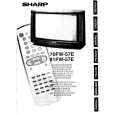
70FW-57E
DESCRIPTION OF SCHEMATIC DIAGRAM
SAFETY NOTE: 1. DISCONNECT THE AC PLUG FROM THE AC OUTLET BEFORE REPLACING PARTS. 2. SEMICONDUCTOR HEAT SINKS SHOULD BE REGARDED AS POTENTIAL SHOCK HAZARDS WHEN THE CHASSIS IS OPERATING. IMPOTANT SAFETY NOTE: PARTS MARKED WITH « »( ) ARE IMPORTANT FOR MAINTAINING THE SAFETY OF THE SET. BE SURE TO REPLACE THESE PARTS WITH SPECIFIED ONES FOR MAINTAINING THE SAFETY AND PERFORMANCE OF THE SET. SERVICE PRECAUTION: THE AREA ENCLOSED BY THIS LINE ( ) IS DIRECTLY CONNECTED WITH AC MAINS VOLTAGE. WHEN SERVICING THE AREA, CONNECT AN ISOLATING TRANSFORMER BETWEEN TV RECEIVER AND AC LINE TO ELIMINATE HAZARD OF ELECTRIC SHOCK. WAVEFORM MEASUREMENT CONDITION: Colour bar genetator signal of 70 dB from RF input.
1 2 3 4
81FW-57E
NOTE: 1. The unit of resistance «ohm»is omitted (K=1000 ohms. M= Megaohm). 2. All resistors are 1/8 watt. unless otherwise noted. 3. All capacitors are µF, unless otherwise noted (P= µµF). 4. The capacitor with Part No. RC-FZ9XXXBMNJ is designed to with stand 63V.
CAUTION This circuit diagram is original one, therefore there may be light difference from yours.
GND GND GND
GND
580V
5 6
1.3 KV 31.25 KHz
7
4 Vp-p 31.25 KHz
8
350 Vp-p
100Hz
GND
41 Vp-p 31.25 KHz
9 10
1.8 Vp-p
100Hz
11
3.3V 100Hz
12
45 Vp-p 113 KHz FM
GND
19V 100Hz
13
25 Vp-p 100Hz
1.15 Vp-p 31.25KHz
400Hz
400Hz
15
|
|
|
> |
|