|
|
|
Categories
|
|
Information
|
|
Featured Product
|
|
|
 |
|
|
There are currently no product reviews.
 ;
This Manual (as downloaded) is both informative and comprehensive and has proved to be extremely useful. thoroughly recommended.
;
everything is ok, thank you very much! Product is good, no problems with download!
;
Great site, I always find all the manuals I need and i can't find anywhere else. PDF for the Sony PCM 3348 is complete and scan is good quality. Thank you!
;
It was a complete manual as stated. Very good source for older product manuals. Thanks
;
Scan quality is very good. Price is very reasonable. If you're looking to purchase a copy of this manual, this is the one to get.
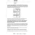
Calibration Procedure for the BBE 882
(REV/S/ON 1.1)
NOTE: THIS UNIT WAS TESTED AND CALIBRATED AT THE FACTORY. THIS PROCEDURE IS FOR QUALIFIED PERSONNEL ONLY. INITIAL SETTINGS: 1. BBE Process controls VR1 and VR3 to minimum.(C.C.W.) 2. Lo Contour controls VR2 and VR4 to minimum.(C.C.W.) 3. Power switch �ON� and BBE function switch �IN�. POWER SUPPLY TEST: 1. With DVM set to DC volts, measure the positive end of C37. You should read less than +30vdc. 2. With DVM set to DC volts, measure the negative end of C39. You should read less than -30vdc. 3. With DVM set to DC volts, measure the voltage on JMP52. Reading should be +15vdc, (+/-0.5vdc). 4. With DVM set to DC volts, measure the voltage on JMP5. Reading should be -15vdc, (+/-0.5vdc). BBE PROCESS TEST: 1. Input a 5khz signal @ -l0dBu into channel A [B] 1/4� jack input. 2. With DVM set to AC volts, measure the channel A [B] 1/4� jack output. 3. With Process control at minimum (C.C.W.) DVM should read -12dBu (+/-1dBu). 4. With Process control at maximum (C.W.) DVM should read +2dBu (+/-1dBu). LO CONTOUR TEST: 1. Input a 50hz signal @ -l0dBu into channel A [B] 1/4� jack input. 2. With DVM set to AC volts, measure the channel A [B] 1/4� jack output. 3. With Lo Contour control at minimum (C.C.W.) DVM should read -13dBu (+/-1dBu). 4. With Lo Contour control at maximum (C.W.) DVM should read +2dBu (+/-1dBu). BYPASS TEST: 1. Input a 500hz signal @ -l0dBu into channel A [B] 1/4� jack input. 2. With DVM set to AC volts, measure the channel A [B] 1/4� jack output. 3. With the process �IN�, DVM should read -9dBu (+/-1dBu) and the Process �IN� LED should be on. 4. With the Process �OUT�, DVM should read -10dBu (+/-1dBu) and the Process �OUT� LED should be on. LED TEST: 1. Return both channels Process and Lo Contour controls to minimum (C.C.W.). 2. Input a 5khz signal @ -18dBu into the channel A [B]1/4� jack input. The yellow -10 LED should light. 3. Change input level to -8dBu. The yellow -10dBu LED should light. 4. Change input level to +2dBu. The green 0dBu LED should light. 5. Change input level to +12dBu. The green +10dBu LED should light. 6. Change input level to +18dBu. The red clip LED should light. XLR TEST: 1. Switch BBE Process �IN�. 2. Input a balanced 5khz signal @ -10dBu into the channel A [B] XLR jack input. 3. Using an oscilloscope, verify the you have a 0.3 volt peak to peak signal on both pins 2 and 3 of the channel A [B] XLR jack output. END TEST.
5381 Production Drive Huntington Beach, CA 92649 (714) 897-6766
12
 $4.99 882 BBE
User Guide It's a complete guide ( also known as operating manual or owner's manual), and it's in PDF format. A…
|
|
|
> |
|