|
There are currently no product reviews.
 ;
Very useful manuals, somewhere graphics not very clear!
 ;
A great manual; it contained all the information I required and allowed me to restore the receiver to full working condition!
;
Very good expirience with owner-manuals.com.
5 Stars; In future if necessary, i´ll download manuals on this site.
;
Hi - happy with what I received but not quite what I wanted - my fault I assumed that service manual would also include operational instructions which is what I needed - all I needed to know was how to turn the radio - thanks
;
this Manual very important when i buy this Manual i already fix the trouble of my Camera..... thanks keep up the good work.!
A-407R
6. ADJUSTMENTS
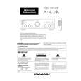
6.1 IDLE CURRENT ADJUSTMENT
¶ CAUTION : Heatsinks� (Q323�Q326) DC level is equal to +B or -B. Don�t touch them or you will be electricary chocked. 1. Connect the measuring instrument as Fig.6-1. (R415 or R416) 2. Set the VOLUME CONTROL to minimum, BASS TONE CONTROL to center, TREBLE TONE CONTROL to center and BALANCE CONTROL to center. Set VR301 and VR302 to minimum. 3. Set the POWER switch to ON. 4. Adjust VR301 (VR302) so that the voltage between both sides of R415 (R416) becomes 16mV±1mV. (Within 10 seconds from when the relay is turned ON) 5. Ages for 7 minutes. 6. Adjust VR301 (VR302) so that the voltage between both sides of R415 (R416) becomes 11mV±1mV.
DC Voltmeter
DC Voltmeter
AF ASSY
SIDE A
R415 R413 W150 Heat Sink VR301 R417 W212
R416 R414
Heat Sink
VR302 Heat Sink
Heat Sink
CN204
Fig.6-1 Adjustment Method
22
|