|
|
|
Categories
|
|
Information
|
|
Featured Product
|
|
|
 |
|
|
There are currently no product reviews.
 ;
Good quality instructions manual. Very useful to me. Quick and excellent service from Owner-Manuals... Thanks !!!
;
Sono molto soddisfatto e, quando mi necessiterà, mi avvarrò nuovamente di questo servizio!
;
A comprehensive Operating and Service Manual. All schematics are complete and easy to read. The PCB drawings and complete parts list are very helpful. I would definitely recommend this manual.
;
SCANNING OF HIGH QUALITY
VERY, VERY HIGH VELOCITY DOWNLOAD
VERY GOOD PRICE,
TRUE SATISFIED, THANKS
;
Genuine Toshiba owner's manual. Couldn't really ask for more. And written in understandable English in contrast to a few recent experiences I have had with manuals for other equipment other than Toshiba but made in China and written in "Chinglish"!
2. Using 2 - #10 - 12 x 1¹��" slot-head wood screws, secure the tray-frame assembly to the wall opening.
3. With tray center pushed away from the windowsill, place a level on the angled edge on top of the tray side. Be sure level is against notch on tray side.
Left Side
A B
A
A. #10 - 12 x 1¹��" slot-head wood screw
A. Angled edge on top of the tray side B. Notch
Right Side
4. Adjust SMART-MOUNT® tray until bubble indicates the angled edge on top of the tray side is level. IMPORTANT: The tray must slope downward slightly toward the outside to provide proper drainage for the air conditioner.
A
B A
A. #10 - 12 x 1¹��" slot-head wood screw
NOTE: If the exterior of building can be damaged by support legs, place a board between the wall and support legs.
A. Bubble indicates the angled edge on top of the tray side is level. B. Place level on angled edge against notch on tray side.
5. Tighten the hex nut just enough to hold tray center in place. 6. Repeat with other side. 7. Tighten hex nuts securely with ����" wrench.
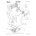
Position the Air Conditioner Through the Wall
s s
Handle air conditioner gently. Be sure your air conditioner does not fall out of the opening during installation or removal. Do not block the louvers on the front panel. Do not block the louvers on the outside of the air conditioner.
s s
WARNING
Excessive Weight Hazard Use two or more people to move and install air conditioner. Failure to do so can result in back or other injury.
1. Place the air conditioner in the SMART-MOUNT® tray. Check that feet on bottom of air conditioner are resting on the ³��" (1.9 cm) x 2" (5 cm) wood strip at the bottom of the wall opening and the top channel rests against the top of the wall opening.
B A
A. SMART-MOUNT® tray B. Feet on bottom of air conditioner resting on wood strip
13
|
|
|
> |
|