|
|
|
Categories
|
|
Information
|
|
Featured Product
|
|
|
 |
|
|
There are currently no product reviews.
 ;
Excellent printing quality. A complete and very useful manual with all details.
 ;
This is a great site. I placed my order and by the next am it was available for download. Had some problems with some missing copy on some pages. Once I brought the error to the OMC's attention, the issue was resolved. I'll come back again.
;
Mi spiace per non poter scrivere in inglese... ma sono veramente soddisfatto del servizio offerto. Grazie..!!
;
The quality of this manual is good. It has all schematics and setup information for both the MDS-B3 and the MDS-B4. The scan quality is quite good, all pages are readable, This service manual also contains scans of the operating instructions from the User manual.
;
Quick site processing. A complete and very useful manual with all details. Thank you!
(5)
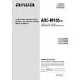
Perform wirings to the C.Bs. Refer to Fig-5/-6; � Be sure to connect the wires coming from the P.W.B. JIG to the same connecting points on the MAIN C.B as follows. 1) Connect the motor wires and sensor (PD201) wires that are removed in step (2) to the P.W.B. JIG. 2) Connect all wires coming from the P.W.B. JIG to the respective lands of the MAIN C.B by soldering. � Connect the motor wires (BLU/WHT) of the P.W.B. JIG to the motor wire connecting lands on the MAIN C.B by soldering. � Connect the LED (LED201) wires (RED/GRY) of the P.W.B. JIG to the LED wire connecting lands on the MAIN C.B by soldering. � Connect the sensor wires (BRN/BLK) of the P.W.B. JIG to the sensor wire connecting lands on the MAIN C.B by soldering. � Connect the sensor (PS201) wires (YEL/ORG/ RED/BRN) of the P.W.B. JIG to the sensor wire connecting lands on the MAIN C.B by soldering. � Connect the SW202 wire (WHT) of the P.W.B. JIG to the SW202 wire connecting lands on the MAIN C.B by soldering. � Connect the SW203 wire (BLK) of the P.W.B. JIG to the SW203 wire connecting lands on the MAIN C.B by soldering. � Connect the SW204 wires (BLU/WHT) of the P.W.B. JIG to the leads of SW204 on the MAIN C.B by soldering. Refer to Fig-6.
Fig-5
Fig-6 (6) How to use the repair jig; When the Control Unit (CDC/CT) is going to be used. 1) After all wires and connections are complete, connect the Control Unit (CDC/CT) with the DIN jack of the P.W.B. FLEX. 2) Connect external power +12 V to ACC/BACKUP wire and ground (-) to the GROUND wire. 3) Perform the operation check. When the Control Unit (CDC/CT) is not used. 1) Connect the supplied P.W.B KEY to the MAIN C.B by performing all connections between them. Refer to Fig-7/-8. (Wires to be used for connecting the MAIN C.B are not supplied.) 2) Connect the wires as follows. Refer to Fig-9.
P.W.B KEY HOT GND
MAIN C.B TO GND
-5-
 $4.99 ADCM105 AIWA
Owner's Manual Complete owner's manual in digital format. The manual will be available for download as PDF file aft…
|
|
|
> |
|