|
|
|
Categories
|
|
Information
|
|
Featured Product
|
|
|
 |
|
|
There are currently no product reviews.
 ;
About one hour after checkout, the manual was available for download. Clear reading and detailed. Thanks
;
Excellent transaction - clean document received - Thanks a lot
;
Manual is in German but complete. I needed this one to fix a long lasting problem with the internal PSU of the camera. Most of the capacitors begin to leak after a few years wich results in the inability to power on the camera. When you try to turn it on the power led flickers and the unit directly turns off. Thanks to this manual I was able to locate all bad cap's and to dis- and reassemble the camera without any problems.
 ;
We received the manual in a timely manner and it was exactly what we were expecting.
;
Excellant, finally this is want I need and searching for The service manual is fantastic and thank you to owner-manuals.com and its service. Price is reasonable. It's a bit slow on my end in downloading but manage to receive the whole manual without a break. once again, thanks.
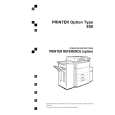
IMAGE FUSING
June 30, 1998
2.9 IMAGE FUSING
2.9.1 OVERVIEW
[A] [F] [G] [E] [D] [J] [K]
[H] [C] [C] [B]
A229D518.WMF
[I]
After the developed latent image is transferred from the drum to the paper, the copy paper enters the fusing unit. Then the image is fused to the copy paper by a heat and pressure process through the use of a hot roller [A] and pressure roller [B]. There are two fusing lamps in the hot roller. Both lamps are 550 W lamps. They switch on and off at the same time. The fusing lamps turn on and off to keep the operating temperature at 185°C. The CPU monitors the hot roller surface temperature through a thermistor [D] which is in contact with the hot roller surface. A thermofuse [E] protects the fusing unit form overheating. The hot roller strippers [F] separate the copy paper from the hot roller and direct it to the fusing exit rollers [G]. The exit sensor in the inverter and paper exit unit monitors the progress of the copy paper through the fusing unit and acts as a misfeed detector while the exit rollers feed the copy paper to the inverter section. The hooking position of the tension springs [H] on the pressure lever [I] adjusts the roller pressure. The oil supply roller [J] applies a light coat of silicone oil to the hot roller. The oil supply cleaning roller [K] remove the paper dust accumulated on the cleaning roller.
2-110
|
|
|
> |
|