|
|
|
Categories
|
|
Information
|
|
Featured Product
|
|
|
 |
|
|
There are currently no product reviews.
 ;
Response is a little slow- I had to wait 12 hours to receive download link but it says that it may take up to 24hrs.
Manual is old and was not produced in PDF- scanned copy is exellent.
Overall- value for money- I recommend
 ;
Excellent quality and quickly delivered manuals at a fair price. Great care is taken in the reproduction process. Even photographs and highly detailed drawings are as clear as in the original. That cannot be said for some freelance manual copies I have obtained from the web. If you have exhausted your internet search of technical manuals, try Owner-Manuals.com. If they do not have it, I do not think it exists. Perhaps, if requested, they may be able to find it. Their resources are certainly greater than most. Shopping here certainly beats waiting for months or years for the manual you seek to appear in an internet auction or garage sale.
;
Very detailed product, also it is a scanning from original, very useful if you have to service this type of amplifier ! Very good product, very hard to find!
;
the Manual was made available as promised, the scans were excellent..Good Work !!!
;
It's complete and helpful manual with good quality of scan. Thanks very much.
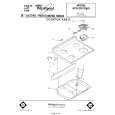
8) Install the eject guide roller belt to the position shown in the figure below.
<2> E clutch unit
1) 2) 3) 4) 5) Remove the cabinet. Remove the main chassis unit. Remove the eject roller unit. Remove the lock of the left bearing. Remove the E clutch unit.
[Note for assembly] Apply grease to the GRE section.
<4> U roller unit
1) 2) 3) 4) Remove the cabinet. Remove the main chassis unit. Remove the locks of the right and left bearings. Remove the U roller unit.
[Note for assembly] Apply grease to the GRE section. 6) Remove the E clutch gear. 7) Remove the bearing. 8) Remove the E clutch roller. 9) Remove the E clutch spring. 10) Remove the E clutch shaft.
[Note for assembly] Clean the CLN section with absolute alcohol.
GRE GRE 5 4 3 2
<5> U left plate unit
1 GRE
1) Remove the cabinet. 2) 3) 4) 5) Remove the main chassis unit. Remove the U roller unit. Remove the feed roller unit. Remove the screw, and remove the U left plate unit.
[Note for assembly] Check that the end of the E clutch spring extends from the concave section of the E clutch roller. Insert the E clutch spring into the square hole of the F arm.
<3> Feed roller unit
1) 2) 3) 4) Remove the cabinet. Remove the main chassis unit. Remove the lock of the left bearing. Remove the feed roller unit.
[Note for assembly] Apply grease to the GRE section.
 $4.99 AJ1800 SHARP
Owner's Manual Complete owner's manual in digital format. The manual will be available for download as PDF file aft…
|
|
|
> |
|