|
|
|
Categories
|
|
Information
|
|
Featured Product
|
|
|
 |
|
|
There are currently no product reviews.
 ;
Excellent quality service manual. Quick processing, fair prices. Love to do business again. Thank you!!!
;
Excellent service manual, the only known point of note is the alignment of improvability scanned pages within the pdf page. The resolution is good.
;
I was very glad recieving the service manal from You. Additionaly very fast. Extremaly nice servicing. Thanks very mach! Now my GX-220 working better, than it was made. Alexander from Moscow, Russia/
;
Sweet! I won the item on eBay and couldn't adjust the geometry or even keep a steady picure. This guide has the full schematics (not available anywhere else as far as I could tell), and was a bargain for the wealth of knowledge it contains. I hooked it up to my testing equipment, tweaked a few potentiometers and got it playing videogames in no time. Thanks!
;
It was just what I need to fix my old BMW's CD player. Very convenient also. Thank you.
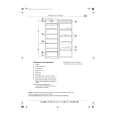
12. OUTPUT CONNECTOR DESCRIPTIONS
12-1. 26 Pin CONNECTOR
The pins in the ISO connector have the following functions (connector seen from the rear)
A. ELECTRIC CONNECTIONS
4. Back-up+12V : YELLOW 5. +12V (electric antenna) : BLUE 6. Dimmer : PINK 7. +12V supply(from ignition lock) : RED 8. Earth : BLACK
B. LOUD SPEAKER
1. +Right Rear 2. - Right Rear 3. +Right Front 4. - Right Front 5. +Left Front 6. - Left Front 7. +Left Rear 8. - Left Rear : VIOLET : VIOLET/BLACK : GRAY : GRAY/BLACK : WHITE : WHITE/BLACK : GREEN : GREEN/BLACK
C. OTHER (OPTION)
5. EARTH 6. TRIP LINE AMPLIFIER(ACC 12V) 8. LINE-OUT(RIGHT) 10. LINE-OUT(LEFT)
D. FUSE
10A
12-2. 8 Pin CONNECTOR
1 2 3 4 5 6 7 8
CDC-ON BACK-UP B+ NO CONNECTION DATA GROUND R-CH L-CH SIGNAL GROUND
29
|
|
|
> |
|