|
|
|
Categories
|
|
Information
|
|
Featured Product
|
|
|
 |
|
|
There are currently no product reviews.
 ;
Perfect copy of the service manual. you can enlarge every page, and it comes up
with all details.
;
It´s very very nice manual with all, what i need. Original in good quality. Very fast business. Very much thanks...
;
Purchased the manual that I was looking for at a great price and could download it easily.. Great service experience and for future purchases I plan to use the site.
Thank you very much
;
Exactly what was needed to assess the product - excellent value and great service
;
A site where discontinualed schematic diagrams and back dated information can be found on discontinued radios tv's and any electronic equipment can be found. Newer manuals either Service and operating manuals. Radio amateurs should find this site a great source for ham radio equipment manuals. I will return to this site should I need information on any electrical equipment. priced easy to download in a PDF format and print pages need to undertake the repair.
8) Move the carriage to the position indicated on the figure. 9) Loosen the screw which is fixing the tension plate. 10) Move the tension plate in the arrow direction to release the tension, and remove the belt.
C. Assembly procedure
CCD core 1) Pass the core through the CCD-MCU harness. 2) Insert the CCD-MCU harness into the CCD PWB connector of the carriage unit.
3)
2)
4)
3) Move the core which was passed through the CCD-MCU harness near the CCD PWB connector as shown in the figure below, and fix it with a filament tape (19mm wide, 40mm long). For the attachment reference, refer to the figure below. Clean and remove oil from the attachment section. 4) Attach the CCD-MCU harness to the duplex tape on the back of the carriage unit. 5) Attach the PWB holder to the position specified in the figure below. 6) Pass the core through the FFC and the PWB holder, and fix the core.
1)
Note: Attach the FFC to the base plate securely with duplex tape to prevent against coming loose.
11) Remove the screw, and remove the rod stopper. 12) Remove the rod.
3)
2) 1) Note: Attach the FFC to fit with the marking line.
13) Lift the rear side of the carriage, remove the belt and the connector, and remove the carriage.
Marking line
4)
1)
2)
3)
AL-1555 DISASSEMBLY AND ASSEMBLY 8 - 4
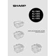 $4.99 AL1456 SHARP
Owner's Manual Complete owner's manual in digital format. The manual will be available for download as PDF file aft… 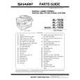 $4.99 AL-1456 SHARP
Parts Catalog Parts Catalog only. It's available in PDF format. Useful, if Your equipment is broken and You need t…
|
|
|
> |
|