|
|
|
Categories
|
|
Information
|
|
Featured Product
|
|
|
 |
|
|
There are currently no product reviews.
 ;
Good quality, all schematics of few of models. There is also short form of user manual and regulation manual.
;
Perfect copy of the service manual. you can enlarge every page, and it comes up
with all details.
;
It´s very very nice manual with all, what i need. Original in good quality. Very fast business. Very much thanks...
;
Purchased the manual that I was looking for at a great price and could download it easily.. Great service experience and for future purchases I plan to use the site.
Thank you very much
;
Exactly what was needed to assess the product - excellent value and great service
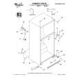
ADJUSTMENTS
1. TUNER SECTION
TEST EQUIPMENT 1. Signal Generator with a frequency range of FM broadcast. 2. Oscilloscope with a side amplifier of approximately 100 KHz.
FM RF SSG FM Antenna Terminal(75 ohm) 75 ohm Coaxal SET Carrier Frequency : 98MHz
3. FM 75/50� dummy antenna. Output Level : 26dBuV Modulation:Audio 1kHZ, 75kHz Deviation 4. VTVM FM ALIGNMENT 1. Turn on the FM signal generator and the VTVM allowing 15 minutes warming-up period. 2. Connect the VTVM across the headphone jack or speaker terminal. 3. Set signal generator frequency as listed in ALIGNMENT CHART and maintain a sufficient output level to provide an indication on VTVM.
NOTE 1. Use a screwdriver with plastic or ceramic grip for all adjustments. 2. Standard test frequency 1 KHz and deviation 75 KHz for FM.
- FM RF, IF ALIGNMENT CHART Step 1 Item FM IF Adjustment Input Circuit Setup Connect stereo signal generator to FM ANT terminal (J001) Connect stereo signal generator to FM ANT terminal (J001) Output Circuit Setup Connect DC voltmeter to edge R201 Tuner Setting FM98MHz75KHz Dev. 26dBµ L203 Adjust forDC 0V±0.1V Adjust for DC 1.17V±0.02V Confirm stereo indicator is lighted and L/R channel is separated. Adjust Point Adjustment
2
Auto Stop Sensitivity
Connect DC voltmeter to edge of RV201
FM 98MHz 75KHz Dev. 26dBµ
RV201
Unless other specified set being switched FM mode, adjust generator's frequency to center of the FM band where no FM broadcast exists Otherwise adjustment of FM usable sensitivity, frequency range for FM band are not needed, but confirm these data are satisfied with specification. CAUTION : When realigning the FM receiving frequency the highest end of the frequency range should not be more than 108 MHz and the lowest end of the frequency range should not be less than 87.5 MHz, in order to comply with FTZ regulation in West Germany.
2. CD SECTION
Note: 1. Use the oscilloscope with more than 10M� impedance. 2. Clean an object lens by an applicator with natural detergent when the signal level is lower than specified value with the following checks.
RF LEVEL CHECK 1. Connect oscilloscope to test point TP502 and IC502 Pin66 on CD PCB. 2. Press power switch on. 3. Put test disc(TCD-781) in and press play button then pause button. 4. Confirm that oscilloscope waveform is clear. Clear RF signal waveform means that the shape"#"can be clearly distinguished at the center of waveform. 5. Adjust RV501 to get a clear waveform and maximum amplitude.
RF Signal Waveform
VOLT/DIV : 200mV TIME/DIV : 50ns
Level : 1.2+0.3Vp-p
4
|
|
|
> |
|