|
There are currently no product reviews.
 ;
Good product and very helpfull to repair. Many thanks.
;
Very good product. Best service manual. Many thanks
;
I am only search for 5 Minute, by it in 5 Minutes to and get ist in few ours! Best i found in the Internet and my Amplifer is repaired as well! Thank you
 ;
Readable text and good copy. Very much needed if you wish to do some repairs on this fine old unit.
;
Fint forløb med levering af manualen. Kvaliteten af skanningen betegnes som middel
1
2
3
4
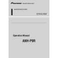
- How to hold the Mechanical Unit
1. Hold the top and bottom frame. 2. Do not squeeze top frame's front portion too tight, because it is fragile.
A
Do not squeeze.
- How to remove the Top and Bottom Frame
1. When the disk is in "clamp" state, unlock Spring A (6
B
Top Frame
pieces) and Spring B (2 pieces), and unscrew screws (4 pieces). 2. Unlock each 1 of pawl at the both side of the frame, then remove the top frame. 3. Remove the Carriage Mechanical part in such way that; you remove the mechanical part from 3 pieces of Damper while slowly pulling up the part. 4. Now, the top frame has been removed, and under this state, fix the genuine Connector again, and eject the disk. (Caution) When you reassemble the Carriage Mechanical part, apply a bit of alcohol to Dampers.
Carriage Mechanical Part
Bottom Frame
Damper
C
- How to remove the Guide Arm Assy
1. Unlock the spring (1 piece) at the right side of the assembly. 2. Unscrew screws (2 pieces), then remove the Screw Gear Bracket. 3. Shift the Guide Arm Assy to the left and slowly rotate it to the upper direction. 4. When the Guide Arm Assy rotates approximately 45 degree, shift the Assy to the right side direction and remove it.
Screw Gear Bracket Guide Arm Assy
D
Spring
58
1 2
ANH-P9R/EW
3 4
|