| » View Shopping Cart | |
 | Quantity: 1 $4.99 » View Details |
 | Quantity: 1 $4.99 » View Details |
 | Quantity: 1 $4.99 » View Details |
 | Quantity: 1 $4.99 » View Details |
 | Quantity: 1 $4.99 » View Details |
 | Quantity: 1 $4.99 » View Details |
 | Quantity: 1 $4.99 » View Details |
 | Quantity: 1 $4.99 » View Details |
 | Quantity: 1 $4.99 » View Details |
 | Quantity: 1 $4.99 » View Details |
 | Quantity: 1 $4.99 » View Details |
 | Quantity: 1 $4.99 » View Details |
 | Quantity: 1 $4.99 » View Details |
 | Quantity: 1 $4.99 » View Details |
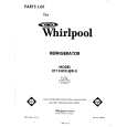 | Quantity: 1 $4.99 » View Details |
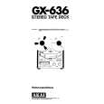 | Quantity: 1 $4.99 » View Details |
 | Quantity: 1 $4.99 » View Details |
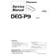 | Quantity: 1 $4.99 » View Details |
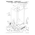 | Quantity: 1 $4.99 » View Details |
 | Quantity: 1 $4.99 » View Details |
 | Quantity: 1 $4.99 » View Details |
 | Quantity: 1 $4.99 » View Details |
 | Quantity: 1 $4.99 » View Details |
 | Quantity: 1 $4.99 » View Details |
 | Quantity: 1 $4.99 » View Details |
 | Quantity: 1 $4.99 » View Details |
 | Quantity: 1 $4.99 » View Details |
 | Quantity: 1 $4.99 » View Details |
 | Quantity: 1 $4.99 » View Details |
 | Quantity: 1 $4.99 » View Details |
 | Quantity: 1 $4.99 » View Details |
 | Quantity: 1 $4.99 » View Details |
 | Quantity: 1 $4.99 » View Details |
 | Quantity: 1 $4.99 » View Details |
 | Quantity: 1 $4.99 » View Details |
 | Quantity: 1 $4.99 » View Details |
 | Quantity: 1 $4.99 » View Details |
 | Quantity: 1 $4.99 » View Details |
 | Quantity: 1 $4.99 » View Details |
 | Quantity: 1 $4.99 » View Details |
 | Quantity: 1 $4.99 » View Details |
 | Quantity: 1 $4.99 » View Details |
 | Quantity: 1 $4.99 » View Details |
 | Quantity: 1 $4.99 » View Details |
 | Quantity: 1 $4.99 » View Details |
 | Quantity: 1 $4.99 » View Details |
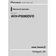 | Quantity: 1 $4.99 » View Details |
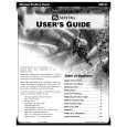 | Quantity: 1 $4.99 » View Details |
 | Quantity: 1 $4.99 » View Details |
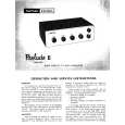 | Quantity: 1 $4.99 » View Details |
 | Quantity: 1 $4.99 » View Details |
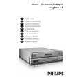 | Quantity: 1 $4.99 » View Details |
 | Quantity: 1 $4.99 » View Details |
 | Quantity: 1 $4.99 » View Details |
 | Quantity: 1 $4.99 » View Details |
 | Quantity: 1 $4.99 » View Details |
 | Quantity: 1 $4.99 » View Details |
 | Quantity: 1 $4.99 » View Details |
 | Quantity: 1 $4.99 » View Details |
 | Quantity: 1 $4.99 » View Details |
 | Quantity: 1 $4.99 » View Details |
 | Quantity: 1 $4.99 » View Details |
 | Quantity: 1 $4.99 » View Details |
 | Quantity: 1 $4.99 » View Details |
 | Quantity: 1 $4.99 » View Details |
 | Quantity: 1 $4.99 » View Details |
 | Quantity: 1 $4.99 » View Details |
 | Quantity: 1 $4.99 » View Details |
| Sub-Total: $339.32 | |


