|
|
|
Categories
|
|
Information
|
|
Featured Product
|
|
|
 |
|
|
There are currently no product reviews.
 ;
Great price, Quick delivery, the document was very usefull A+++++++++++++++
;
Great price, Quick delivery, the document was very usefull A+++++++++++++++
;
Great price, Quick delivery, the document was very usefull A+++++++++++++++
;
Great price, Quick delivery, the document was very usefull A+++++++++++++++
;
Great price, Quick delivery, the document was very usefull A+++++++++++++++
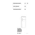
AR-405 * Note for assembling the copy lamp unit Move the copy lamp unit to the paper exit side, and fix the copy lamp unit wiht the harness guide so that the distance between the copy lamp harness and the lower frame is about 25 ~ 30 mm with the copy lamp harness extended. Shift the copy lamp unit to the paper exit side, and fix it with the harness guide so that the distance from the lower frame is about 24 ± 2mm with the copy lamp harness extended. After fixing, manually shift the copy lamp unit a few times to check that it moves smoothly. If the copy lamp harness is loosely fixed, the copy lamp unit may jump up when reading, resulting in abnormal reading. AR-2XX/3XX series
(2) Vertical image distortion balance adjustment (No. 2/3 mirror base unit installing position adjustment)
This adjustment is to adjust the parallelism of the mirror base to the OPC drum surface and the original surface. 1) Manually turn the mirror base drive pulley to bring mirror base B into contact with mirror base positioning plate. If, at that time, the front frame side and the frame side of mirror base B are brought into contact with the mirror base positioning plate simultaneously, the parallelism is correct and there is no need for adjustment.
24±2mm
AR-405
(3) Sub scanning direction distortion adjustment (Winding pulley position adjustment)
This adjustment is executed in the following cases:
25±30mm
� � �
When the mirror base drive wire is replaced. When the lamp unit, or No. 2/3 mirror holder is replaced. When a copy shown below is made.
La Lb
Paper exit direction Original Copy
1/21/1999
7�8
|
|
|
> |
|